
Vane pump

A technology of vane pumps and vane plates, applied in pumps, pump components, pump control, etc., can solve problems such as high processing and assembly costs, and achieve the effects of improving sealing, reducing friction radius, and reducing processing costs

Inactive Publication Date: 2013-07-24
欧根·施密特博士仪器和泵制造有限责任公司
View PDF22 Cites 6 Cited by
  • Summary
  • Abstract
  • Description
  • Claims
  • Application Information

AI Technical Summary

Problems solved by technology

[0029] However, the major disadvantages of all the aforementioned constructions are not only the high manufacturing and assembly costs necessary to minimize frictional losses and radial clearances of the blades and thus leakage losses (volume losses) and to achieve the desired efficiency, but also to The large structural outer diameter that is necessarily required to form an effective displacement chamber even with structurally and process-related relatively narrow fillable chamber widths, wherein the large inner diameter of the outer ring necessarily leads to centrifugal force-induced High frictional torque (at the outer ring)

Method used


Image

  • Vane pump
  • Vane pump
  • Vane pump

Examples


Embodiment Construction

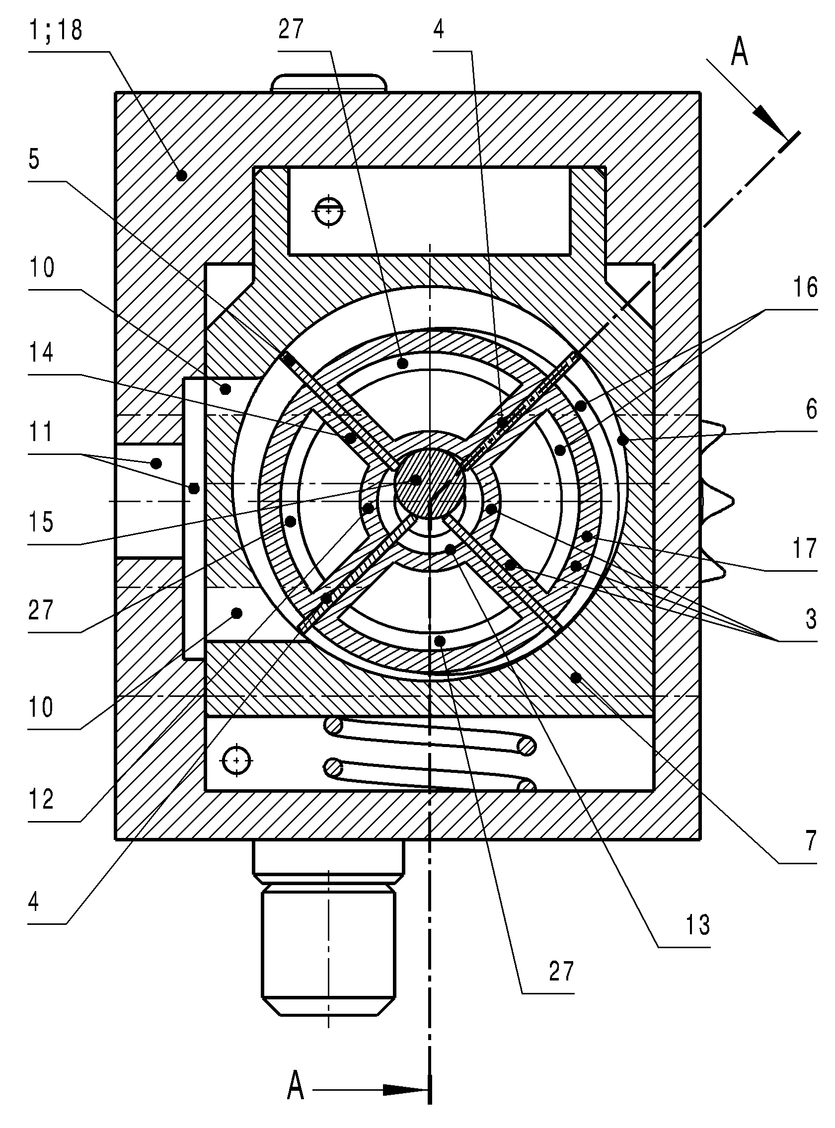
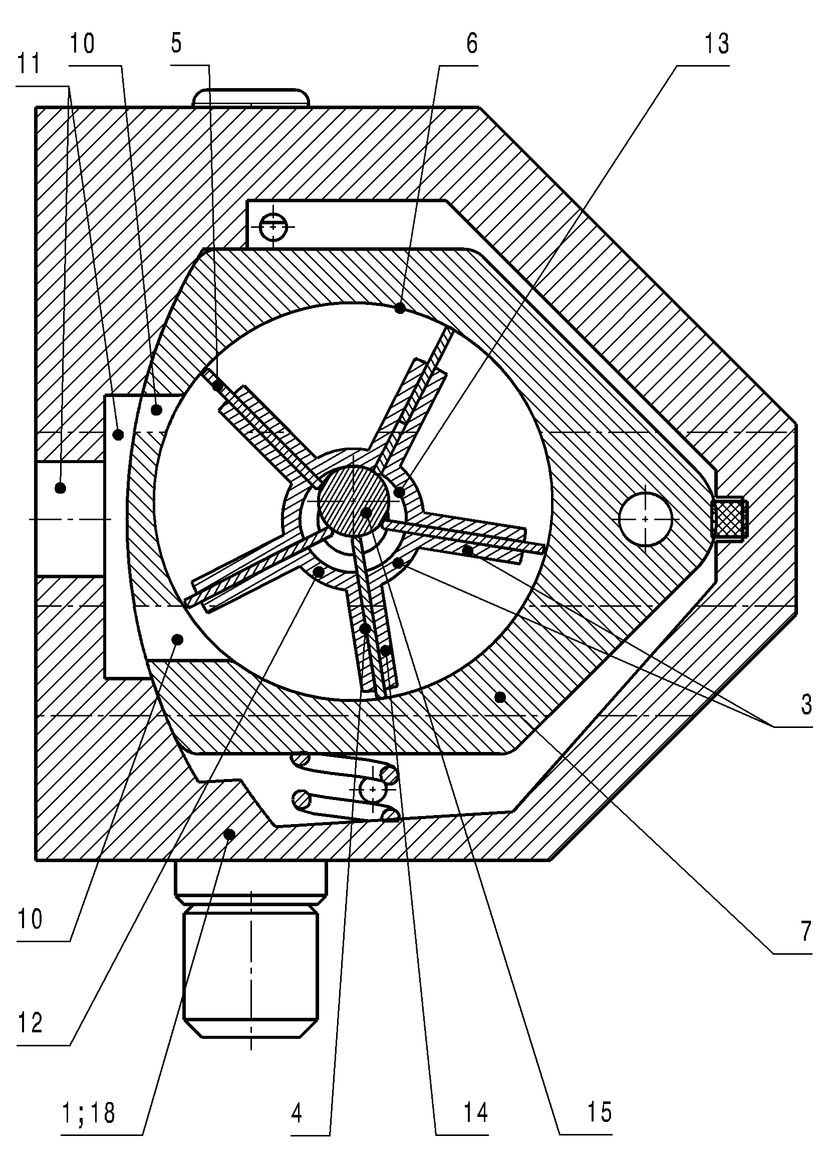
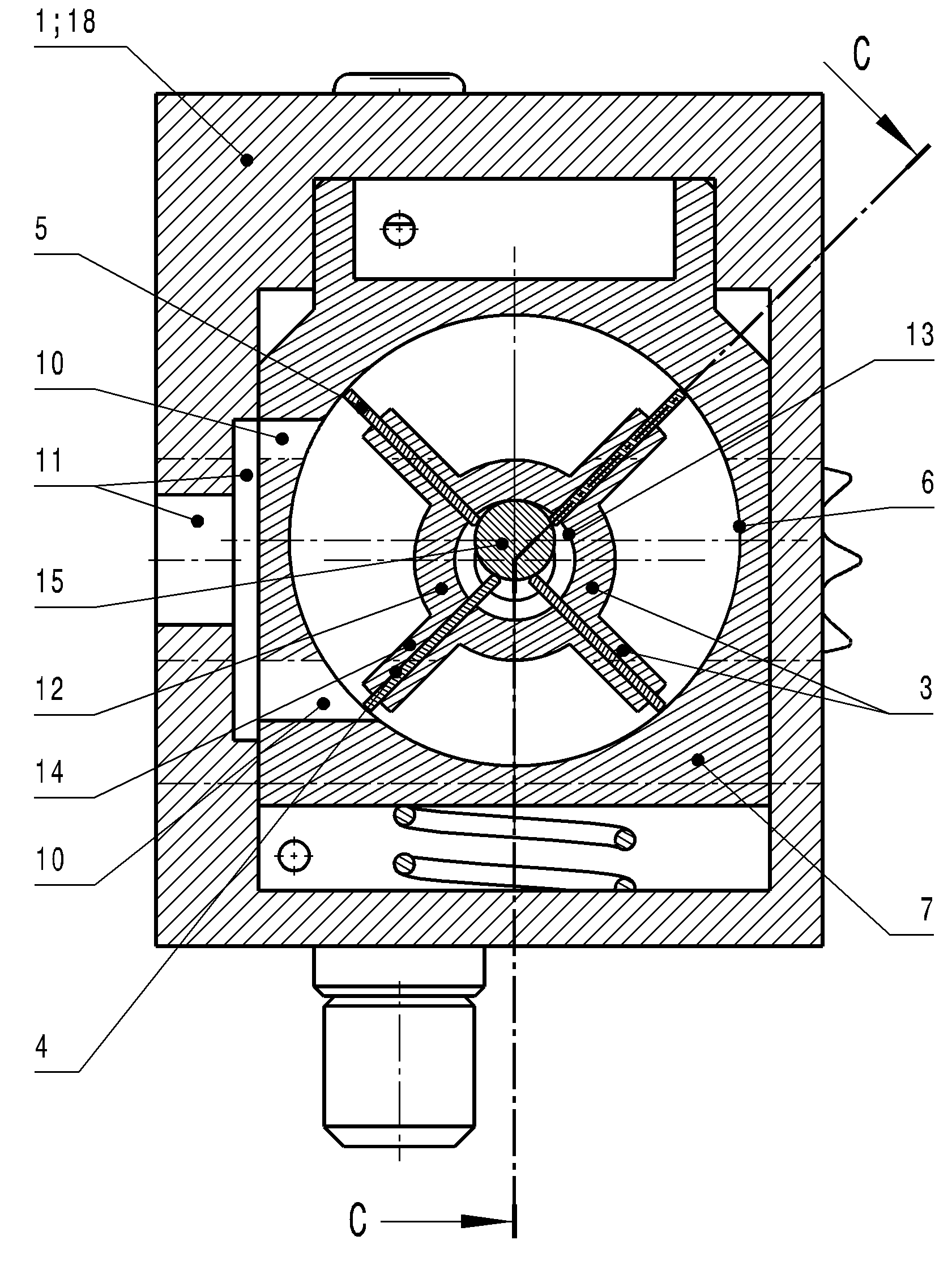
[0054] Four of the possible designs of the vane pump according to the invention are shown in FIGS. 1 to 6 with two different designs of the adjusting slide 7 .

[0055] Common to all designs here is that the rotor shaft 12 is arranged in the pump housing 1 .

[0056] The rotor shaft 12 comprises a drive shaft 2 mounted in the pump housing 1 and a hollow rotor shaft 24 connected to the drive shaft 2 .

[0057] All constructions are characterized in that a cylindrical guide 13 is arranged in the rotor hollow shaft 24 , in which a freely surrounding synchronous cylinder 15 which is non-rigidly connected to adjacent components is guided .

[0058] What is essential according to the invention here is that the blade-shaped, associated bearing groove 4 arranged in the wall of the rotor hollow shaft 24 is arranged so rigidly on the rotor hollow shaft 24 that in the region of this bearing groove 4 there is Approximately 0.75 to 1.8 times the diameter of the synchronizing cylinder 15 ...


PUM


Abstract

The invention relates to a vane pump, comprising a rotor, which is supported in a pump housing and driven by a shaft, a plurality of vane plates supported in the rotor in a radially movable manner, and an outer ring that surrounds the rotor and the vane plates, the outer ring being arranged either directly in the pump housing or in an adjusting ring that can be moved in the pump housing along specified paths. The invention is based on the aim of developing a vane pump that among other things lowers the frictional and leakage losses, ensures the pump chambers are filled and drained optimally in regard to flow, in the lower rotational speed ranged as well as in the upper rotational speed range, significantly reduces the power losses, also is easy to manufacture and assemble in regard to production and significantly reduces the production costs, at the same time is insensitive to particles, minimizes the wear of the assemblies, and ensures the reliability and service life and a high specific delivery volume flow at high volumetric efficiency, both at low rotational speeds and high rotational speeds. The vane pump according to the invention is characterized in particular in that a cylinder guide (13) is arranged in the hollow rotor shaft (24), in which cylinder guide a freely rotating synchronizing cylinder (15) that is not rigidly connected to the adjacent assemblies is guided, wherein vane-shaped vane plate guide webs (14), which are associated with bearing grooves (4) arranged in the wall of the hollow rotor shaft (24) and which radially protrude beyond the hollow rotor shaft (24) in the vicinity of said bearing grooves (4) by approximately 0.75 to 1.8 times the diameter of the synchronizing cylinder (15) and which have bearing grooves (4), are rigidly arranged on the hollow rotor shaft (24) in such a way that the hollow rotor shaft (24) forms a vane rotor (3) together with vane plate guide webs (14), and outlet opening(s) (10), which extend completely through the adjusting slide and which extend radially with respect to the inner cylinder (6) and which are opposite the inlet nodule(s) (9) arranged in the side walls of the pump housing (1) on the pump side, are arranged in the adjusting slide (7).

Description

technical field [0001] The invention relates to a vane pump (Flügelzellenpumpe) with a shaft-driven rotor mounted in a pump casing, a plurality of radially displaceable vane plates (Flügelplatte) mounted in the rotor, and surrounding the rotor and The outer ring of the vane plate, wherein the outer ring is arranged either directly in the pump housing or in an adjusting ring movable along a predetermined path in the housing. Background technique [0002] Various embodiments of vane pumps are already known in the prior art. Thus, for example, DE 29 14 282 C2 and DE 103 53 027 A1 each describe adjustable vane pumps with a linearly displaceable adjusting ring for achieving a variable output power. [0003] Usually on both sides of the rotor of a vane pump, a suction kidney (Saugniere) is arranged on one side and a pressure kidney (Druckniere, sometimes also called to excrete the kidney). [0004] It is also characteristic of both above-mentioned embodiments that the blade pla...

Claims


Application Information

Patent Timeline
Patent Type & Authority Applications(China)
IPC IPC(8): F04C2/344F04C15/00F04C15/06F04C18/344F04C29/00F04C29/12
CPCF01C21/0836F04C2/3442F04C14/223F04C14/226F04C2240/20F04C2/00
Inventor F.帕韦莱克
Owner 欧根·施密特博士仪器和泵制造有限责任公司
Learn More