

Electromagnetic generator
A technology of electromagnetic generators and magnets, applied in the direction of electromechanical devices, electrical components, etc., can solve the problems of long effective length, large deflection, and inability to obtain sufficient power, and achieve the effect of improving efficiency
- Summary
- Abstract
- Description
- Claims
- Application Information
AI Technical Summary
Problems solved by technology
Method used
Image

Examples
Embodiment 1)
[0054] Hereinafter, one embodiment (Example 1) of the electromagnetic generator according to the present invention will be described with reference to FIGS. 1 to 10 .
[0055] As shown in Figure 1, the electromagnetic generator 1 has: a magnet assembly 3, a magnet holder 12, and a guide rod 11 to guide the movement of the magnet assembly 3; housings 23, 24 to hold the guide rod 11 from both ends; The repelling magnets 4 and 5 of the device function as magnetic springs, repel the magnet assembly 3 , the case 22 , and the solenoid coil 21 , and generate electric power by electromagnetic induction with the magnet assembly.
[0056] The housings 23, 24 are formed of circular plates.
[0057] The guide rod 11 is formed of a round rod. In addition, the guide rod 11 is provided so as to extend from the center of one surface of the circular plate forming the housings 23 and 24 in a direction perpendicular to the other surface.
[0058] The magnet holder 12 is mounted so that the gui...
Embodiment 2)
[0081] 11 and 12 show the electromagnetic generator 1 according to the second embodiment.
[0082] As shown in FIG. 11 , the electromagnetic generator 1 is equipped with: a magnet assembly 3; holding parts 27, 28, which hold the magnet assembly 3 along the moving direction; a housing 8, which accommodates the holding parts 27, 28; and a solenoid coil 21, which passes Electricity is generated by electromagnetic induction with the magnet assembly 3 .
[0083] Holders 27 and 28 are composed of housings 23 and 24 and repelling magnets 4 and 5 . Furthermore, the holding parts 27 and 28 have a distance adjustment mechanism for adjusting the distance between the holding parts 27 and 28 and the magnet assembly 3 . Specifically, the casings 23, 24 have male threads formed on their outer peripheries, and are provided with recesses for accommodating the repelling magnets 4, 5 and grooves 25, 26 into which the front ends of tools such as a flat-blade screwdriver fit. Rotation enables mo...
Embodiment 2
[0094] (Modification 1 of Embodiment 2)
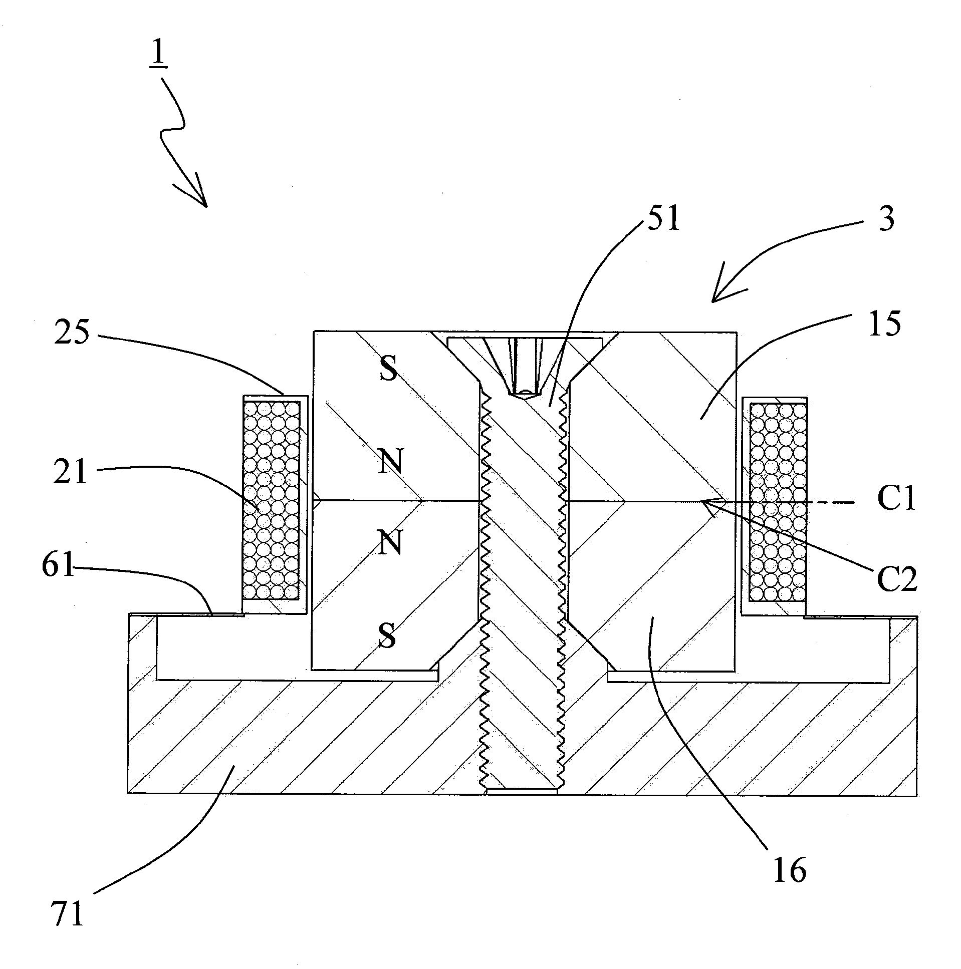
[0095] FIG. 13 shows an electromagnetic generator 1 according to Modification 1 of Embodiment 2. In FIG.
[0096] The same reference numerals are assigned to the same configuration as that of the second embodiment shown in FIG. 11 , and description thereof will be omitted.
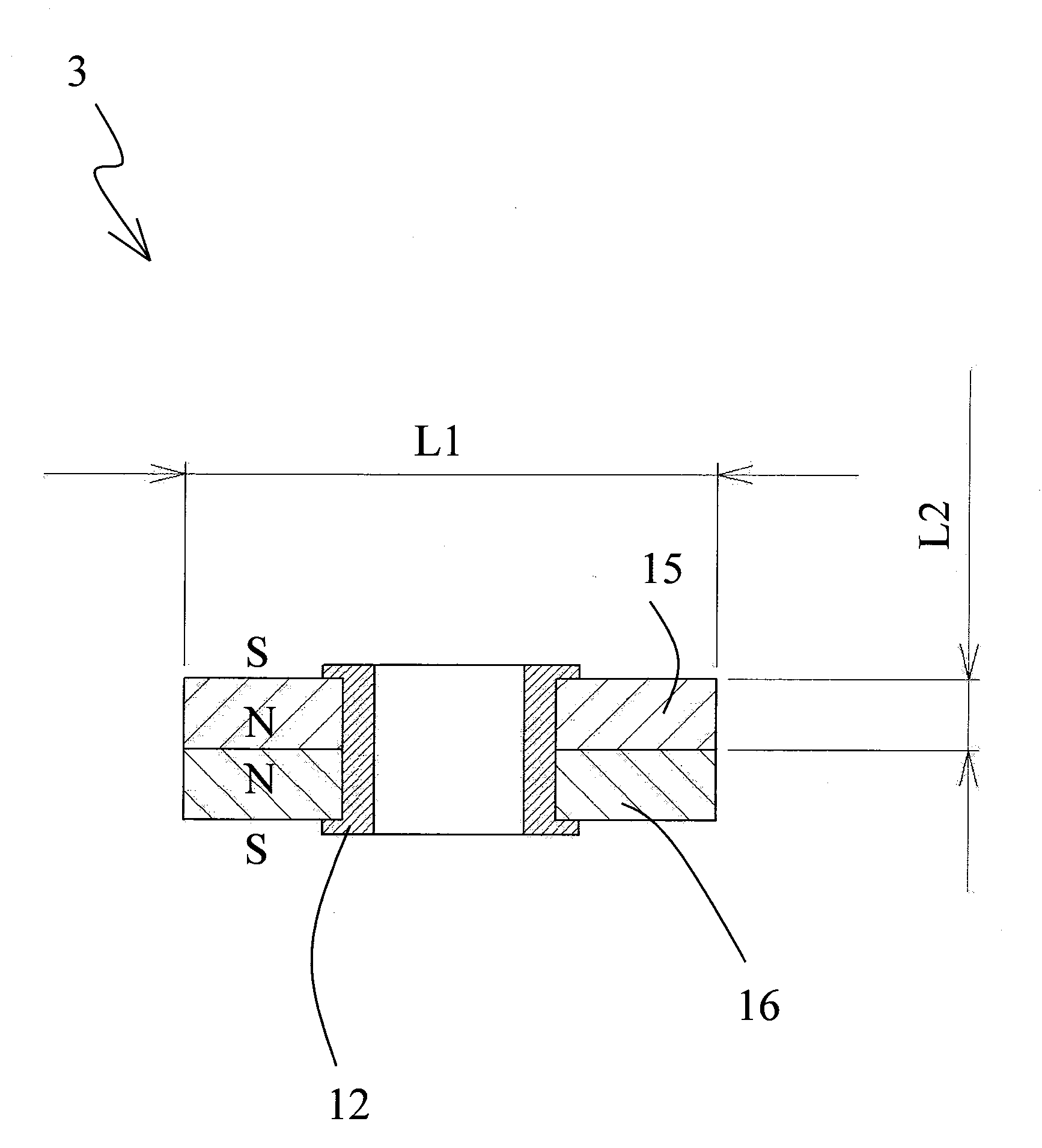
[0097] The difference between Example 2 and Modification 1 of Example 2 is that unit magnets 15 and 16 are fastened by countersunk screws 14 with cross holes and nuts 13 to form magnet assembly 3 .
[0098] The repelling magnets 4 and 5 are fixed to the housings 23 and 24 by bonding, with their opposite poles of the same polarity as the magnet assembly 3 facing the magnet assembly 3 .
[0099] The unit magnets 15 and 16 are magnets with a counterbore having a center hole and a conical chamfer on one side of the hole. Insert the countersunk screw 14 and the nut 13 with the cross hole into the central holes of the unit magnets 15 and 16 , fasten the countersunk scr...
PUM
 Abstract
Description
Claims
Application Information