Replacement method of coupling between reducer and hydraulic coupler of stacker

A technology of hydraulic coupler and replacement method, applied in metal processing, metal processing equipment, manufacturing tools, etc., can solve the problem of difficult disassembly and assembly, large volume and weight, increased maintenance time and maintenance cost of cantilever belt conveyors, etc. problems, to achieve the effect of reducing labor intensity, improving replacement efficiency, and reducing replacement steps

Active Publication Date: 2013-07-31
CHINA SHENHUA ENERGY CO LTD +1
View PDF2 Cites 3 Cited by
  • Summary
  • Abstract
  • Description
  • Claims
  • Application Information

AI Technical Summary

Problems solved by technology

[0003] It can be understood that in the driving device of the cantilever belt conveyor, each device has a large volume and weight, which makes disassembly and assembly difficult
Moreover, since the coupling between the hydraulic coupling and the reducer is installed in the brake of the reducer, after replacing the coupling, it is difficult to ensure the coaxiality between the reducer and the motor and the hydraulic coupling, resulting in Repeated disassembly and assembly are required, which reduces the maintenance efficiency of the cantilever belt conveyor and increases the maintenance time and cost of the cantilever belt conveyor

Method used


Image

  • Replacement method of coupling between reducer and hydraulic coupler of stacker

Examples


Embodiment Construction

[0024] Specific embodiments of the present invention will be described in detail below in conjunction with the accompanying drawings. It should be understood that the specific embodiments described here are only used to illustrate and explain the present invention, and are not intended to limit the present invention.

[0025] In the present invention, unless stated otherwise, the orientation words used such as "up, down, left, right" usually refer to the upper, lower, left, and right in the drawings, and "inner, outer" refers to Inside and outside relative to the outline of the part.

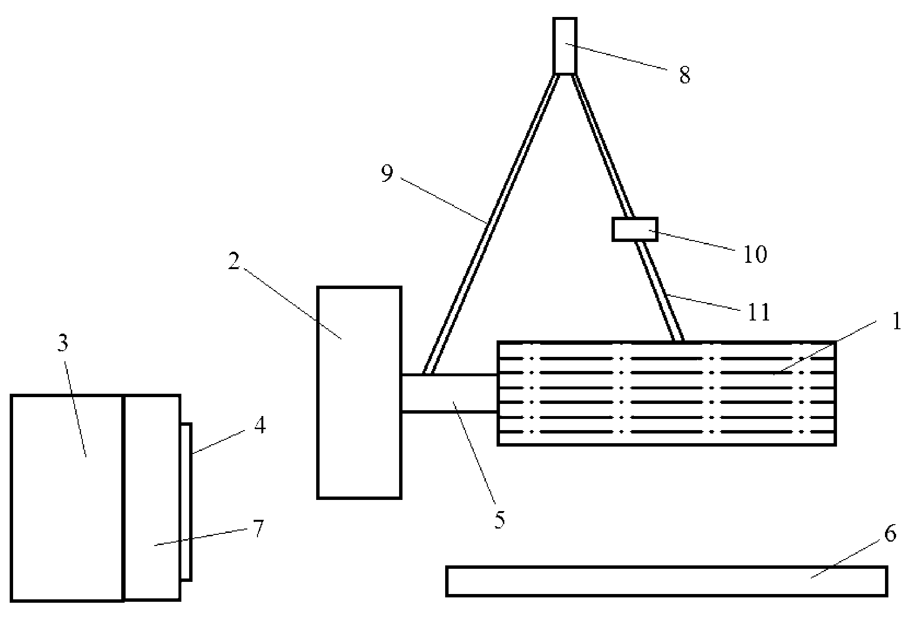
[0026] see figure 1 , in the cantilever belt conveyor of the stacker, the motor 1, the hydraulic coupler 2, and the reducer 3 are connected in sequence to transmit the power of the motor to the driving roller connected to the reducer 3 (for display). When the coupling 4 between the speed reducer 3 and the fluid coupling 2 is eccentric, the coupling 4 needs to be replaced. The invention relate...


PUM


Abstract

The invention discloses a replacement method of a coupling between a reducer and a hydraulic coupler of a stacker. According to the invention, the stacker comprises a motor (1) and a base (6) on which the motor is mounted; and the hydraulic coupler (2) is connected with the motor. The replacement method further comprises the following steps: step 1, cutting the connection between the coupling (4) and the hydraulic coupler, as well as the connection between the motor and the base; step 2, suspending the unit composed of the hydraulic coupler and the motor; step 3, replacing the coupling mounted on the reducer (3); step 4, laying down the unit composed of the hydraulic coupler and the motor, and connecting the replaced coupling with the hydraulic coupler, and finally mounting the motor on the base. The replacement method has higher replacement efficiency, lower replacement strength, and better ensures coaxiality.

Description

technical field [0001] The invention relates to the maintenance field of engineering machinery, in particular to a method for replacing a shaft coupling between a reducer of a stocker and a hydraulic coupling. Background technique [0002] In the cantilever belt conveyor of the stacker, the driving device of the cantilever belt conveyor connects the motor, hydraulic coupling and reducer in sequence through a coupling. Among them, due to reasons such as transmission eccentricity, the coupling often needs to be replaced. [0003] It can be understood that in the driving device of the cantilever belt conveyor, each device has a large volume and weight, which makes disassembly and assembly difficult. Moreover, since the coupling between the hydraulic coupling and the reducer is installed in the brake of the reducer, after replacing the coupling, it is difficult to ensure the coaxiality between the reducer and the motor and the hydraulic coupling, resulting in Repeated disassem...

Claims


Application Information

Patent Timeline
Patent Type & Authority Applications(China)
IPC IPC(8): B23P19/00
Inventor 李建光陈冰杨宏展张延军王敏刚韩斌马光辉肖雄建
Owner CHINA SHENHUA ENERGY CO LTD
Why Eureka
Try Eureka