Phase plane self-adaptation control method based on characteristic model

A technology of adaptive control and feature model, which is applied in aircraft control, flight direction control, aircraft parts, etc., can solve problems such as plume interference and large flexibility of sailboards, and achieve the effect of solving system delays

Active Publication Date: 2013-07-31
BEIJING INST OF CONTROL ENG
View PDF5 Cites 12 Cited by
  • Summary
  • Abstract
  • Description
  • Claims
  • Application Information

AI Technical Summary

Problems solved by technology

[0009] The technical problem of the present invention is: to overcome the need for human-controlled trial and error in the existing phase plane control design parameters, to provide a parameter design method for phase plane control, to solve the problem of large flexibility

Method used


Image

  • Phase plane self-adaptation control method based on characteristic model
  • Phase plane self-adaptation control method based on characteristic model
  • Phase plane self-adaptation control method based on characteristic model

Examples


Embodiment 1

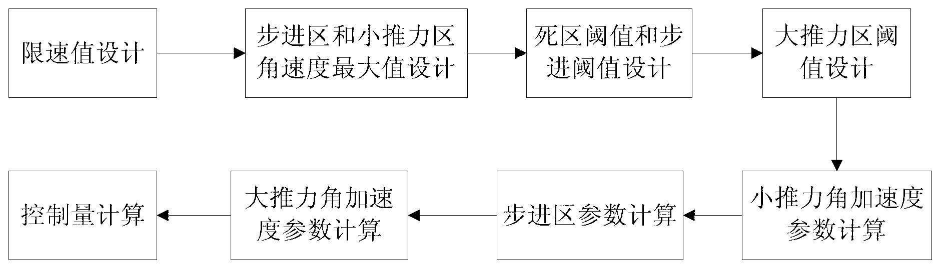
[0048] The realization steps of the present invention are as follows:

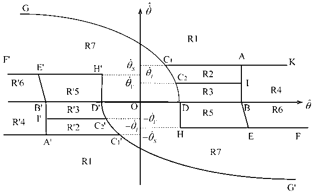
[0049] (1) According to the system delay ΔT delay and dynamic performance requirements to design the speed limit value in the jet control law Let the system delay be ΔT delay , large thrust angular acceleration a JL , the control performance requires that the allowable range of angular velocity is Then the speed limit value in the jet control law can be designed make it satisfy and θ · L = [ θ · min , θ · max ] .

[0050] (2) According to the system dynamic performance requirements, and consider the speed limit value designed in step (1) Designing the Maximum Angular Velocity in the Stepping Region in the Jet Control Law an...

Embodiment 2

[0070] The method for adaptively adjusting the phase plane parameters according to the characteristic parameters is given below.

[0071]If the horizontal and vertical axes of the phase plane are replaced by relative position and relative velocity, the phase plane control method can also be applied to translation control. In the rendezvous and docking section, the tracker approaches the target along the docking corridor. As the longitudinal relative distance decreases, the accuracy of lateral position control is required to gradually increase. At this time, the longitudinal relative distance can be selected as the characteristic parameter, and the phase plane parameters that affect the control accuracy can be adaptively adjusted according to the characteristic parameter to achieve the control goal.

[0072] Referring to Example 1, the phase plane parameters are designed. With the decrease of the longitudinal relative distance, the requirement of lateral position control accu...


PUM


Abstract

Disclosed is a phase plane self-adaptation control method based on a characteristic model. The method comprises the following steps: (1) a speed limit value in a jet control law is designed; (2) an angular speed maximum value of a stepped zone, an angular speed maximum value of a low thrust zone, a dead zone theta D and a stepped threshold value theta v in the jet control law are designed; (3) a high thrust zone threshold value theta B in the jet control law is designed; (4) a low thrust angular speed accelerated speed parameter ac2 and a high thrust angular speed accelerated speed parameter ac1 in the jet control law are calculated according to a golden ratio coefficient; (5) a stepped zone parameter kjj in the jet control law is calculated according to the low thrust angular speed accelerated speed parameter ac2, and a parabola coefficient KX in the jet control law is calculated according to the high thrust angular speed accelerated speed parameter ac1 and other phase plane parameters; (6) the controlled quantity is calculated according to parameters designed in the above-mentioned steps and a phase plane jet control logic, namely, the jet length of an engine is confirmed, and the engine is controlled within a sampling control period according to the confirmed control quantity.

Description

technical field [0001] The invention relates to a method for controlling the phase plane of a spacecraft, in particular to a high-precision and stable jet control method for a flexible spacecraft that has disturbances such as plumes and system time delays during the rendezvous and docking process. Background technique [0002] Space rendezvous and docking refers to the entire flight process in which two spacecraft meet (rendezvous) at a predetermined position, speed, and time in orbit, and then align and move closer through attitude alignment until they are structurally connected as one (docking). The two spacecrafts performing rendezvous and docking in space are usually called a target vehicle (referred to as a target vehicle), and the other is called a tracking vehicle (referred to as a tracker). During the rendezvous and docking process, the tracker is active, and the rendezvous and docking of the two spacecraft is generally achieved in stages by changing the position and...

Claims


Application Information

Patent Timeline
IPC IPC(8): B64C15/00
Inventor 解永春胡军吴宏鑫胡海霞张昊
Owner BEIJING INST OF CONTROL ENG
Why Eureka
Try Eureka