Fluid pressure supply device of transmission

A fluid pressure, supply device technology, applied in transmission control, components with teeth, belts/chains/gears, etc., can solve problems such as insufficient hydraulic pressure, no solution, etc.

Active Publication Date: 2013-07-31
HONDA MOTOR CO LTD
View PDF6 Cites 7 Cited by
  • Summary
  • Abstract
  • Description
  • Claims
  • Application Information

AI Technical Summary

Problems solved by technology

[0007] By configuring the technology described in Patent Document 1 as described above, the self-priming performance of the small-capacity hydraulic pump can be improved, but this is because the small-capacity hydraulic pump and the large-capacity hydraulic pump are always driven by the same rotational driving force of the drive source. Premise, therefore, in the case of intermittently driving a small-capacity hydraulic pump, it is also conceivable that the hydraulic pressure is insufficient between the small-capacity hydraulic pump and the 3rd check valve, so the above-mentioned problem is not solved

Method used


Image

  • Fluid pressure supply device of transmission
  • Fluid pressure supply device of transmission
  • Fluid pressure supply device of transmission

Examples


Embodiment

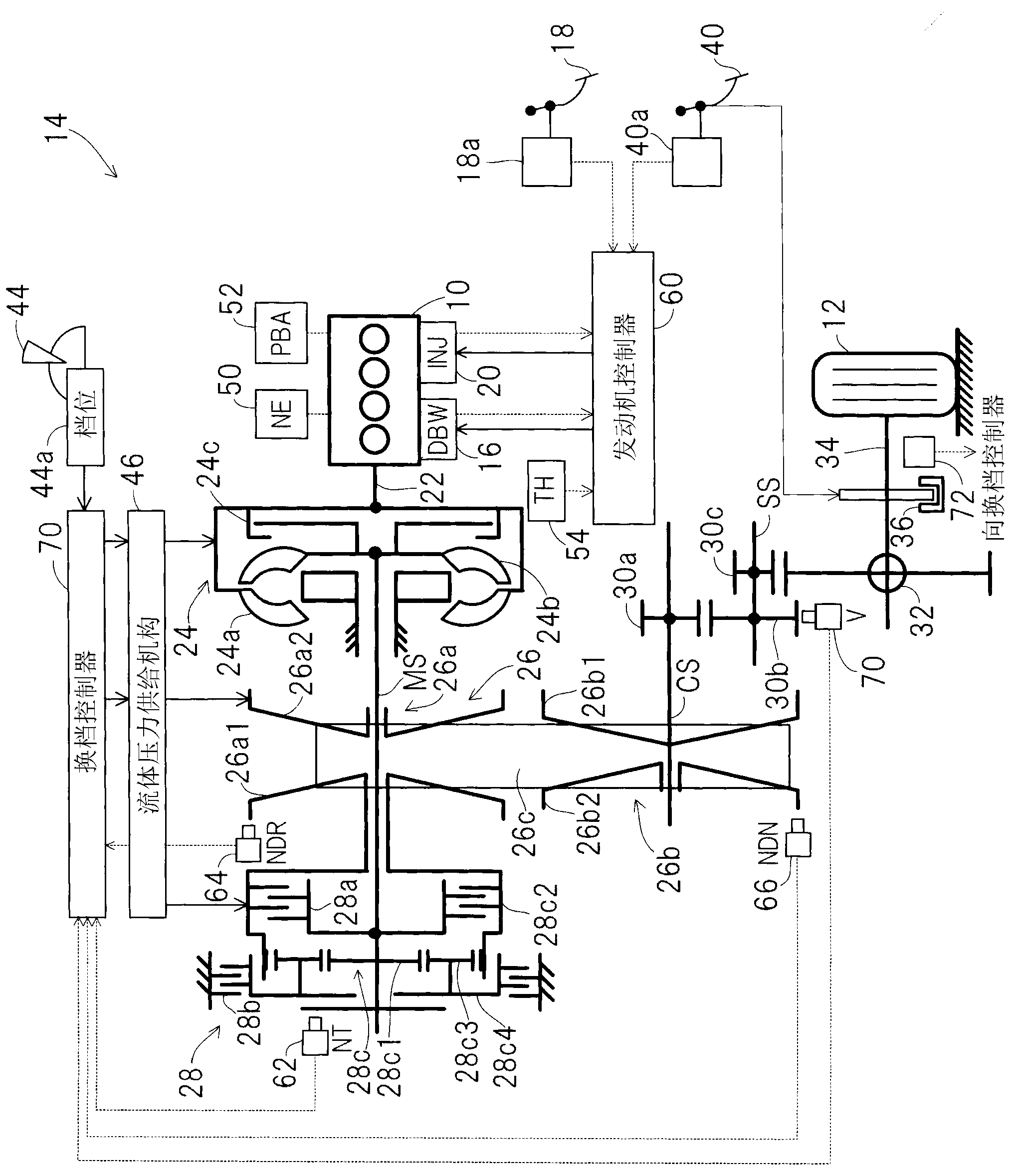
[0021] figure 1 It is a schematic diagram which shows the fluid pressure supply apparatus of the transmission of the embodiment of this invention as a whole.

[0022] exist figure 1 In , reference numeral 10 denotes an engine (internal combustion engine (drive source)). The engine 10 is mounted on a vehicle 14 including driving wheels (wheels) 12 (the vehicle 14 is partially shown by the driving wheels 12 and the like).

[0023] The throttle valve (not shown) arranged in the air intake system of the engine 10 is disconnected from the mechanical connection with the accelerator pedal 18 arranged on the driver's seat floor of the vehicle, and is connected to the DBW (Drive By Wire) composed of actuators such as electric motors. : drive by wire) mechanism 16 is connected, and is opened and closed through DBW mechanism 16.

[0024] The intake air regulated by the throttle valve flows through the intake manifold (not shown), and is mixed with the fuel injected from the fuel injec...


PUM


Abstract

The inveniton provides a fluid pressure supply device of transmission, which comprises a first and a second fluid pressure pumps respectively driven by the first and the second driving powers, and can improve the self-absorption of working fluid of the second fluid pressure pump. The device comprises a liquid pressure pump (46c) which is driven by an engine carried on the vehicle for discharging the liquid pressure to an oil way (46e) connected to the belt wheel of CVT; a first and a second pressure regulating valve (46l, 46m) for inputting the discharged fluid pressure, and the pressure is outputted from the channle formed by ring groove etched on the valve column for supplying to the belt wheel, moreover, the leakage part of the inputted liquid pressure is discharged from a second output port (46l6, 46m6); an electric hydraulic pump (46mm) driven by an electric motor (74) for discharging the liquid pressure, moreover, the second output port (46l6, 46m6) of the first and the second pressure regulating valve are connected to a suction inlet (46mm1) of the electric hydraulic pump through oil way (46vv, 46ww, 46xx).

Description

technical field [0001] The present invention relates to a fluid pressure supply device for a transmission, and more specifically, to a device including two hydraulic (fluid pressure) pumps for supplying fluid pressure such as hydraulic pressure to components of a transmission. Background technique [0002] The fluid pressure supply device of the transmission usually has a mechanical hydraulic (fluid pressure) pump driven by the rotational driving force of the driving source such as the engine mounted on the vehicle. Fluid) and pressurized hydraulic pressure (fluid pressure) is supplied to the components of the transmission. [0003] In addition, a structure has been proposed that includes an electrohydraulic pump driven by a second drive source such as an electric motor in addition to the hydraulic pump, and improves hydraulic responsiveness by intermittently driving the electrohydraulic pump. , Depending on the operating state, air remains in the suction port of the electr...

Claims


Application Information

Patent Timeline
Patent Type & Authority Applications(China)
IPC IPC(8): F16H61/44F16H61/662
Inventor 宫田智西村尚己石川知朗仲野茂司
Owner HONDA MOTOR CO LTD
Why Eureka
Try Eureka