Overflow no-damage multiphase mixed transmission pump

A mixed and flow-through technology, which is applied to radial flow pumps, pumps, components of pumping devices for elastic fluids, etc., can solve problems affecting the stable operation of the system, high vibration and noise during operation, and human health hazards. Achieve the effect of improving self-priming performance, good anti-cavitation performance and reducing damage

Active Publication Date: 2020-06-12
JIANGSU UNIV
View PDF7 Cites 2 Cited by
  • Summary
  • Abstract
  • Description
  • Claims
  • Application Information

AI Technical Summary

Problems solved by technology

[0002] With the continuous development of the national economy and the gradual improvement of the quality of life of residents, food safety has also received more and more attention. There are problems such as low transportation efficiency, high self-priming requirements, and large overcurrent damage, which not only makes the transportation cost higher, but also leads to product deterioration when the damage is serious, causing harm to human health
At present, volumetric and axial-flow screw pumps are mainly used in the field of multi-phase transportation. These pumps are large in volume and high in cost, so the scope of use is limited.
Centrifugal pumps have the characteristics of high efficiency, reliable operation, and wide application range, but they are easy to cause damage to the conveyed materials
In addition, centrifugal pumps are sensitive to gas and solid media, and have high vibration and noise during operation. The performance of the pump will deteriorate rapidly under high gas content and high liquid-solid ratio, which will affect the stable operation of the system.

Method used


Image

  • Overflow no-damage multiphase mixed transmission pump
  • Overflow no-damage multiphase mixed transmission pump
  • Overflow no-damage multiphase mixed transmission pump

Examples


Embodiment Construction

[0022] The technical solution of the present invention will be described in further detail below in conjunction with the accompanying drawings.

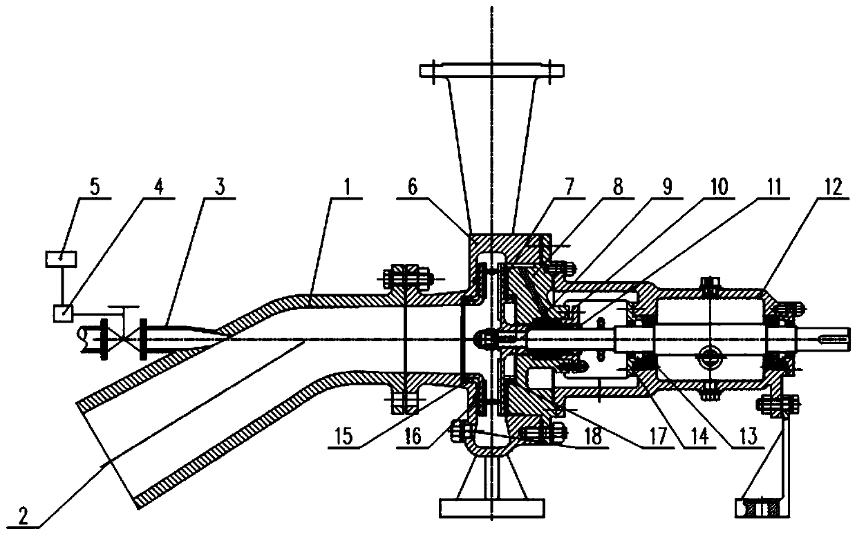
[0023] combine figure 1 and figure 2 , a flow-through lossless multi-phase mixed pump, comprising: suction pipe 1, interception net 2, conical shrinking nozzle 3, gas mass flow controller 4, controller 5, pump body 6, impeller 7, pump cover 8 , pump shaft 9, mechanical seal 10, sleeve 11, suspension 12, bearing 13, end cover 14, first front port ring 15, second front port ring 16 rear port ring 17, bottom valve 18, inlet of suction pipe 1 An interception net 2 is installed, and a conical constricting nozzle 3 is installed at the elbow of the suction pipe 1. The conical constricting nozzle 3 is connected to the gas mass flow controller 4. The conical constricting nozzle 3 communicates with high-pressure gas, and the gas mass flow rate The controller 4 is connected to the controller 5. The pump body 6 is provided with an impeller 7 ...


PUM


Abstract

The invention discloses an overflow no-damage multiphase mixed transmission pump. The pump comprises a suction pipe, an interception net, a conical shrinkage nozzle, a gas mass and flow controller, acontroller, a pump body, an impeller, a pump cover, a pump shaft, a mechanical seal, a sleeve, a suspension, a bearing, an end cover, front impeller rings, a rear impeller ring and a bottom valve, wherein a front cover plate and a rear cover plate of the impeller are connected through a connecting rod, the front cover plate and the rear cover plate are provided with six long radial blades and sixshort radial blades which are evenly distributed along the axis line of the pump shaft, the middle of an impeller flow passage is a bladeless area, the impeller is connected with the pump shaft through a key and is positioned in the pump body, the conical shrinkage nozzle is installed at the front end of the suction pipe through the axis line of the pump shaft, the suction pipe is connected with an inlet of the pump body, and a volute of the pump body is an annular volute. The pump has the advantage of no damage, no blockage, good self-absorption performance, stable operation, strong cavitation resistance and the like, and can be applied to the multiphase transportation fields such as live fishes, live shrimps and foods like sauce, edible oil and jelly.

Description

technical field [0001] The invention relates to a pumping device, which is applicable to the field of multiphase transportation, in particular to a flow-through and non-destructive multiphase mixed transportation pump. Background technique [0002] With the continuous development of the national economy and the gradual improvement of the quality of life of residents, food safety has also received more and more attention. There are problems such as low transportation efficiency, high self-priming requirements, and large overcurrent damage, which not only makes the transportation cost higher, but also leads to product deterioration when the damage is serious, which is harmful to human health. At present, volumetric and axial-flow screw pumps are mainly used in the field of multi-phase transportation. These pumps are large in volume and high in cost, so the scope of application is limited. Centrifugal pumps have the characteristics of high efficiency, reliable operation, and w...

Claims


Application Information

Patent Timeline
Patent Type & Authority Applications(China)
IPC IPC(8): B65G53/24B65G53/34B65G53/52F04D1/00F04D9/06F04D29/22F04D29/42F04D29/66
CPCB65G53/24B65G53/34B65G53/52F04D1/00F04D9/065F04D29/22F04D29/426F04D29/669
Inventor 司乔瑞廖敏泉王彪彪王鹏袁建平袁寿其
Owner JIANGSU UNIV
Why Eureka
Try Eureka