Centrifugal pump

a centrifugal pump and centrifugal pump technology, applied in specific fluid pumps, non-positive displacement pumps, fluid engines, etc., can solve the problems of insufficient elaborate measures and the low degree of freedom in designing the shape of the distal ends of the vanes, and achieve the effects of promoting the generation of vortex flows, and promoting the generation of air bubbles

Active Publication Date: 2018-02-27
HONDA MOTOR CO LTD
View PDF11 Cites 2 Cited by
  • Summary
  • Abstract
  • Description
  • Claims
  • Application Information

AI Technical Summary

Benefits of technology

[0009]With this arrangement, since the flow-channel recess portion opens to the volute internal flow channel and is formed so as to be recessed in the direction orthogonal to the direction of flow of the fluid, at a time of performing a self-priming operation, gas (air) in the volute case is mixed (or entrained) with the prime fluid in a state of air bubbles. By virtue of the air bubbles contained in the prime fluid, the viscosity and density of the prime fluid are reduced so that the prime fluid can be easily introduced in an internal space of the flow-channel recessed portion.
[0018]On the other hand, the sufficiently small protruding part located adjacent to the leading end of the volute case is able to appropriately suppress generation of the vortex flow by the prime fluid (i.e., stirring of the prime fluid). The prime fluid guided to a leading end of the volute internal flow channel is smoothly discharged from the leading end of the volute internal flow channel. This will provide a high prime-fluid pumping performance. By virtue of a combination of the enhanced generation of air bubbles on the trailing end side of the volute internal flow channel and the suppressed generation of the vortex flow on the trailing end side of the volute internal flow channel, the gas in the volute internal flow channel can be appropriately discharged to the outside and a further improvement in the self-priming performance can be achieved.

Problems solved by technology

Under these circumstances, the degree of freedom in designing the shape of the vanes' distal ends is considerably low, and sufficient elaborately measures cannot be taken to form the distal ends of the vanes into a shape which is suitable for performing a steady operation.

Method used


Image

  • Centrifugal pump
  • Centrifugal pump
  • Centrifugal pump

Examples


Embodiment Construction

[0035]A certain preferred structural embodiment of the present invention will be described in greater details below, by way of example only, with reference to the accompanying sheets of drawings.

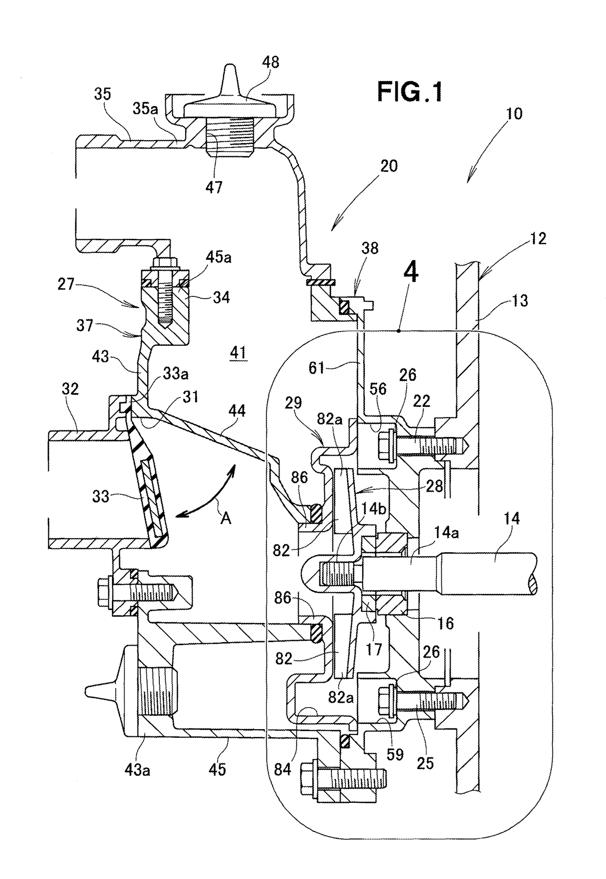
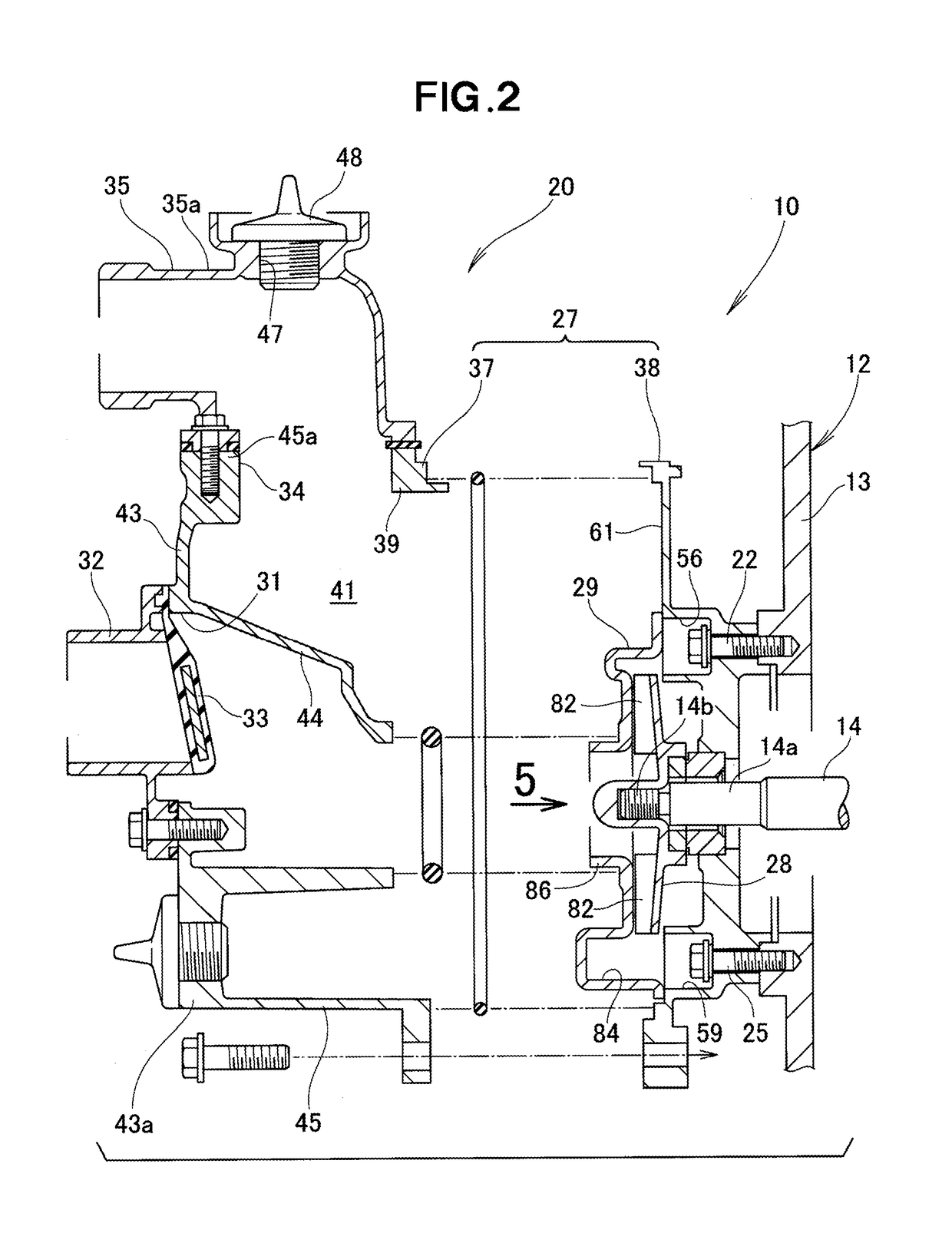
[0036]As shown in FIG. 1, a centrifugal pump unit 10 generally comprises a base (not shown) supporting the centrifugal pump unit 10, an engine 12 including a cylinder block 13 mounted on the base, and a centrifugal pump 20 provided on the cylinder block 13 of the engine 12.

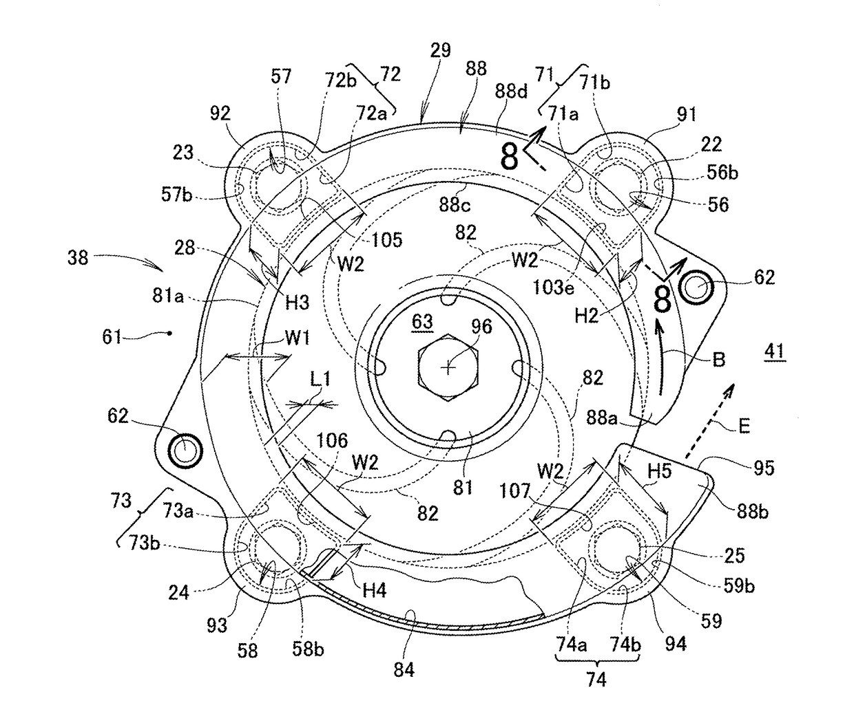
[0037]The engine 12 includes the cylinder block 13 mounted on the base, and a crankshaft (output shaft) 14 rotatably supported inside the cylinder block 13. The centrifugal pump 20 has a case member 27 (especially, a partition member 38 of the case member 27) mounted to the cylinder block 13 by first to fourth bolts 22-25 (the second and third bolts 23, 24 being shown in FIG. 5). A sealing washer 26 is disposed between each of the bolts 22-25 and the partition member 38 (especially, a volute support wall 61 of the partitio...


PUM


Abstract

A centrifugal pump includes an impeller rotatably disposed in a volute case for forcing a fluid to flow along a volute internal flow channel formed in the volute case, and first to fourth flow-channel recessed portions opening to the volute internal flow channel. The first and fourth flow-channel recessed portions are formed so as to be recessed in a direction substantially orthogonal to a direction of flow of the fluid. In a self-priming operation, the fluid is introduced into the first and fourth recessed portions whereupon the prime fluid is stirred within internal spaces of the first and second flow-channel recessed portions.

Description

FIELD OF THE INVENTION[0001]The present invention relates to a centrifugal pump configured to force a fluid to flow along a volute internal flow channel upon rotation of an impeller disposed in a volute case.BACKGROUND OF THE INVENTION[0002]Centrifugal pumps generally include a volute provided inside a casing, and an impeller provided on a rotating shaft projecting into the volute. The impeller has a hub mounted on the rotating shaft and a plurality of vanes provided on the hub. The impeller is disposed inside the volute. When the centrifugal pump is to be driven, a self-priming operation is performed to create a negative pressure inside the volute to thereby introduce a fluid, such as water, into the volute by the effect of the negative pressure.[0003]By thus introducing the fluid via the self-priming operation, a steady operation becomes possible. In the steady operation, the fluid is first sucked into the volute, then guided outside the volute (i.e., inside the casing) by the eff...

Claims


Application Information

Patent Timeline
Patent Type & Authority Patents(United States)
IPC IPC(8): F04D29/42F04D7/04F04D9/02
CPCF04D29/426F04D29/4273F04D9/02F04D7/04
Inventor TSURUDA, KOUKIAKIYAMA, MASAHIROOKABE, KAKU
Owner HONDA MOTOR CO LTD
Why Eureka
Try Eureka