Rotor housings for disconnecting mechanisms of switching devices for electrical switchgear

A technology for rotor shells and electrical switches, which is applied in the direction of electrical switches, circuit breakers with excessive current, electrical components, etc., can solve the problems of costly locking, high complexity, and complexity limitations, and achieve reduced friction and high mechanical efficiency. Effects of stability, reduced complexity and manufacturing cost

Inactive Publication Date: 2017-03-01
SIEMENS AG
View PDF7 Cites 0 Cited by
  • Summary
  • Abstract
  • Description
  • Claims
  • Application Information

AI Technical Summary

Problems solved by technology

[0004] The disadvantage of the known rotor housing is that it is limited in its complexity when manufactured in one part
If a two-part housing is required, it must be cost-intensive to ensure the support of the housing interior and the locking of the housing
This requires not only additional assembly steps but also a high level of complexity for the structural design of the individual housing elements

Method used


Image

  • Rotor housings for disconnecting mechanisms of switching devices for electrical switchgear
  • Rotor housings for disconnecting mechanisms of switching devices for electrical switchgear
  • Rotor housings for disconnecting mechanisms of switching devices for electrical switchgear

Examples


Embodiment Construction

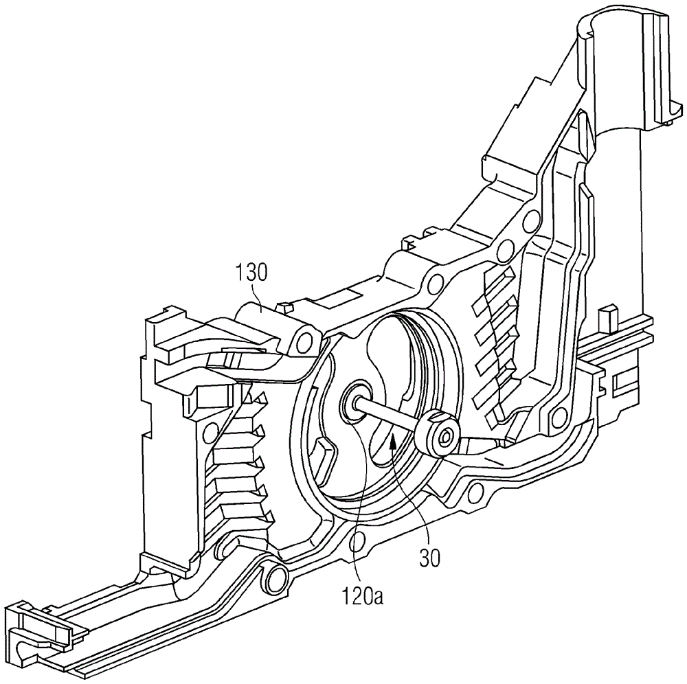
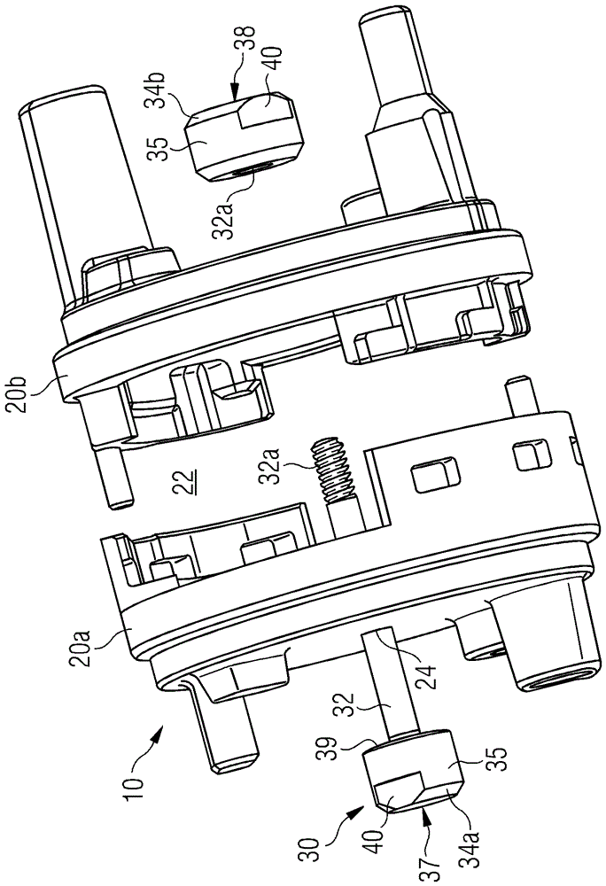
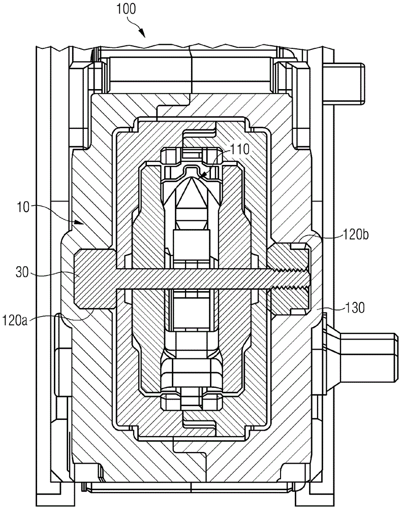
[0064] figure 1 with 2 A first embodiment of a rotor housing 10 according to the invention is shown. The rotor housing 10 has two housing elements 20a and 20b, for example figure 2 can be separated from each other as shown. Furthermore, a connecting element 30 is provided, the shaft section 32 of which passes through the interior of the rotor housing 10 , ie the housing interior 22 . As a result, the shaft section 32 is located in the housing interior 22 , for example Figure 4 The swivel support structure forming part of the breaking mechanism 110 as shown in FIG.

[0065] To locally fix the two housing elements 20 a and 20 b relative to one another, the connecting element 30 has a head section 37 and a base section 38 . The head section 37 and the base section 38 each have a contact surface 39 which bears on the outer side of the respective housing element 20a and 20b. if available in Figure 3a with 3b As seen in , since the connecting element 30 has a mounting mea...


PUM


Abstract

The housing (10) has a housing element (20a) and another housing element (20b) that together forms a casing interior (22) for receiving of an opening mechanism. A connecting element (30) is utilized for locally connecting the former housing element and the latter housing element with each other. The connecting element has a shaft section (32) for rotary storage of a part of the opening mechanism. The connecting element comprises a set of opposite ends (30a, 30b) and a set of bearing units (34a, 34b). Independent claims are also included for the following: (1) a switching device (2) a method for assembly of a switching device.

Description

technical field [0001] The invention relates to a rotor housing for an opening mechanism of an electrical switching device, in particular a switching device for a circuit breaker, a switching device for an electrical switching device, such an electrical switching device and for mounting a switching device Methods. Background technique [0002] It is known to provide disconnecting mechanisms for electrical switching devices, in particular circuit breakers, in order to provide automatic disconnection of electrical circuits in a desired manner. Such electrical switching devices are also used, for example, as fused short-circuiters. In this case, the disconnection mechanism generally has a contact bridge or a plurality of contact bridges, which are movable between a contacted position state and a non-contact position state. The disconnecting mechanism is here movable between these two positions, that is to say between an on position and an off position, so that a corresponding...

Claims


Application Information

Patent Timeline
Patent Type & Authority Patents(China)
IPC IPC(8): H01H1/22
CPCH01H1/2041H01H1/2058H01H73/045
Inventor J.比尔纳W.费尔登A.希尔
Owner SIEMENS AG
Why Eureka
Try Eureka