Strand casting system

An equipment and continuous casting technology, applied in the field of continuous casting equipment, can solve the problems of undesired transition errors and reaction forces, and achieve the effects of easy assembly, simplified maintenance, and avoidance of orientation errors

Active Publication Date: 2015-07-15
SMS DEMAG AG
View PDF10 Cites 0 Cited by
  • Summary
  • Abstract
  • Description
  • Claims
  • Application Information

AI Technical Summary

Problems solved by technology

This can lead to undesired transition errors and reaction forces on the strand shell (which is still very thin in the upper region of the strand guide)

Method used


Image

  • Strand casting system

Examples


Embodiment Construction

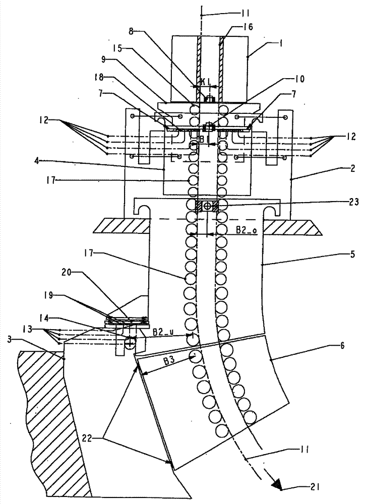
[0027] A vibrator base frame 2 is arranged below the casting table or turret. The vibrator vibration frame 9 that is supported on the vibrator base frame 2 and can be vibrated by the drive device of the vibrator base frame 2 belongs to the vibrator base frame 2, and the vibrator vibration frame 9 itself accommodates Cast crystallizer 1.

[0028] The first strand guide section 4 is connected to the vibrating frame of the vibrator or the continuous casting mould.

[0029] The other strand guides are formed by strand guide sections 5 , 6 etc., wherein only two strand guide sections are also shown in the figures, namely the second strand guide section 5 and the third strand guide section. Blank guide section 6.

[0030] Designated with 3 is the segment support frame on which the second strand guide segment 5 is supported with its underside, wherein the bearing point is designated with 14 .

[0031] The second strand guide section 5 is supported with its top side in the region o...


PUM


Abstract

The invention relates to a strand casting system, comprising a strand casting mold, which is inserted into an oscillator oscillating frame, an oscillator base frame, which accommodates the oscillator oscillating frame, and a strand guide, which is connected to the strand casting mold and which comprises a plurality of strand guide segments, which are provided with strand guide rollers and which are supported on a segment support frame. According to the invention, the strand casting mold can be positioned with respect to the oscillator oscillating frame by means of a horizontal fixing point, the first strand guide segment is supported on the oscillator base frame and can be horizontally oriented thereon at a bearing point on the oscillator base frame, the second strand guide segment can be oriented in the region of the inlet-side strand guide rollers at a bearing point on the oscillator base frame, and the second strand guide element is supported at the base region thereof on the segment support frame in order to determine the horizontal and vertical position.

Description

technical field [0001] The invention relates to a continuous casting equipment (Stranggie?anlage), comprising a continuous casting crystallizer (Stranggie? kokille) placed in a vibratory vibrating frame, a vibrator base frame accommodating the vibrating vibrating frame and a vibrator base frame connected to the continuous casting crystal The strand guide at the device comprises a plurality of strand guide segments which are provided with strand guide rollers and are supported on a segment support frame. Background technique [0002] Usually in continuous casting installations the uppermost or first strand guide segment is mounted on a segment support frame or a vibrator base frame. [0003] In this regard, examples are taken from documents JP 63005858, US 3 409 070, US 4 799 535 and US 4 953 614. [0004] As long as the support is at the section support frame it is problematic because the section support frame is subject to thermal growth. [0005] However, reference point...

Claims


Application Information

Patent Timeline
Patent Type & Authority Patents(China)
IPC IPC(8): B22D11/04B22D11/053B22D11/128B22D11/14B22D11/041
CPCB22D11/053B22D11/041B22D11/141B22D11/1281
Inventor J.霍夫迈斯特P.约嫩M.热普齐克
Owner SMS DEMAG AG
Why Eureka
Try Eureka