a cutting machine
A cutting machine and cutting nozzle technology, applied in metal processing equipment, welding equipment, manufacturing tools, etc., can solve the problems of difficult to achieve incision accuracy, difficult to achieve cutting, difficult to ensure technical quality, etc.
- Summary
- Abstract
- Description
- Claims
- Application Information
AI Technical Summary
Problems solved by technology
Method used
Image

Examples
Embodiment 1
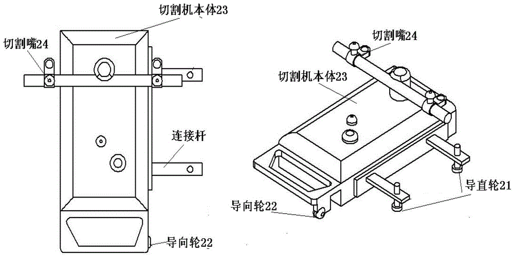
[0029] like figure 2 As shown, it is a plan view and a perspective view. The present invention proposes a cutting machine, comprising: a cutting machine body 23, a cutting nozzle 24, a straightening wheel 21, and a guiding wheel 22, wherein the cutting nozzle 24 and the straightening wheel 21 are respectively located at the On both sides of the cutting machine body 23, the straightening wheel 21 is connected to one side of the cutting machine body 23 through a connecting rod, and the guiding wheel 22 is fixed on the cutting machine body 23, and the sliding direction of the straightening wheel 21 is It is consistent with the sliding direction of the guide wheel 22; when the cutting machine body 23 is placed on the top of the material to be cut and forms a contact surface, the guide wheel 22 is in sliding contact with the contact surface; The edge of the contact surface protrudes and descends to the side of the material to be cut and is in sliding contact with the side; the gui...
Embodiment 2
[0034] like Figure 5 shown, combined with figure 2 , the present invention proposes another implementation of a cutting machine, on the same side of the cutting nozzle 54 of the cutting machine body 53, it also includes the straightening wheel 51 connected to the cutting machine body 53 through a connecting rod The sliding direction of the guide wheel 52 is consistent with the sliding direction of the guide wheel 52. The guide wheel 51 protrudes from the edge of the contact surface on the side of the cutting nozzle 54 through the connecting rod and descends to the edge of the material to be cut. The sides of the side are in sliding contact with the sides to form a track direction.
[0035] like Image 6shown, according to Figure 5 For further explanation, a scenario where two straightening wheels are installed on both sides of the cutting machine body is given as an example. Both sides of cutting machine body 63 are respectively equipped with two straightening wheels 61...
Embodiment 3
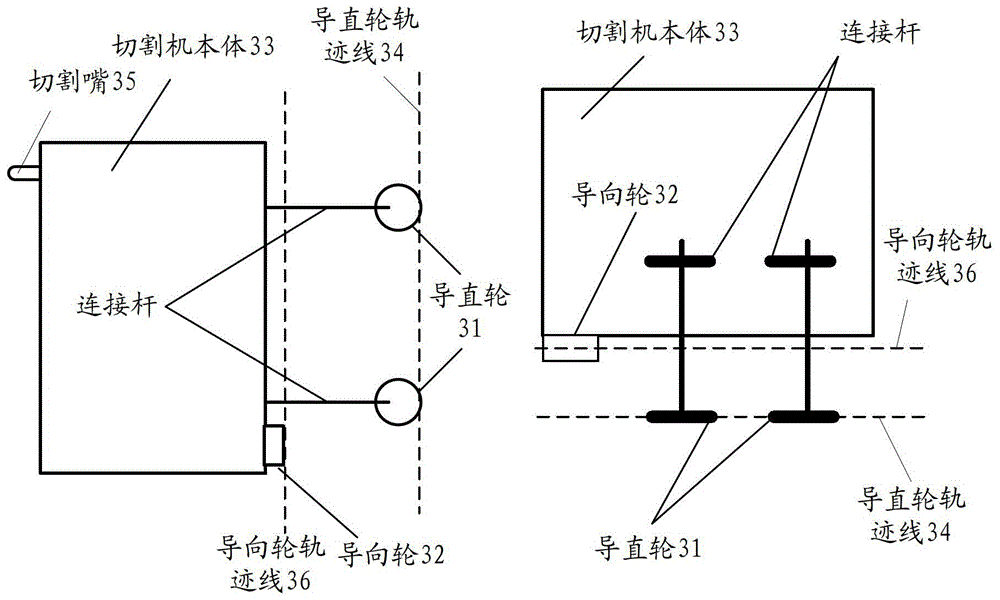
[0040] like Figure 7 As shown, it is a schematic diagram of implementation of the present invention that straightening wheels are installed at both ends of the cutting machine body. Here is an example of a scenario where two guide wheels are installed on the bottom surface of the cutting machine body in contact with the cutting surface, and the sliding tracks between the guide wheels are not on the same straight line. like Figure 7 As shown, two straightening wheels 71 are installed on one side of the cutting machine body 73, and the structure of the two straightening wheels 71 can refer to image 3 and Figure 4 structure, which will not be repeated here. At this time, the setting of the guide wheel 72 can be at one end of the cutting machine (the side where the guide wheel 71 is installed) and the other end (the side of the cutting nozzle 75) and the position of the surface in contact with the cutting material, such as Figure 7 As shown, the guide wheel trajectory lin...
PUM
 Abstract
Description
Claims
Application Information