
Eureka
For R&D, Eureka makes reading and utilizing patents & technical documents easy.
Eureka AIR
Designed for self-driven R&D workflows. Generate viable solutions, solve complex R&D challenges, empower your innovation with AI.

Eureka Materials
Designed for material experts only. Revolutionize your material R&D, from search, analyze, to developing new materials.

TechResearch
Generate reliable direction feasibility study reports for your R&D in just a few steps.

TechSeek
Discover and master advanced knowledge NOW. Basics, ideas, possibilities, all at once.

TechMind
As an expert in R&D Theories, TechMind can generates customized viable solutions instantly.

TechRisk
Analyze your overall solution with one click, know your potential R&D risks in advance.

TechMonitor
Get weekly tech updates, stay abreast of the latest tech innovations and key insights.
Continuous extruding machine for hollow concrete slabs
A hollow concrete and extruder technology, used in ceramic molding machines, ceramic extrusion dies, manufacturing tools, etc., can solve the problems of wasting manpower and low production efficiency, and achieve the effect of improving quality
- Summary
- Abstract
- Description
- Claims
- Application Information
AI Technical Summary
Problems solved by technology
Method used
Image

Examples
Embodiment 1
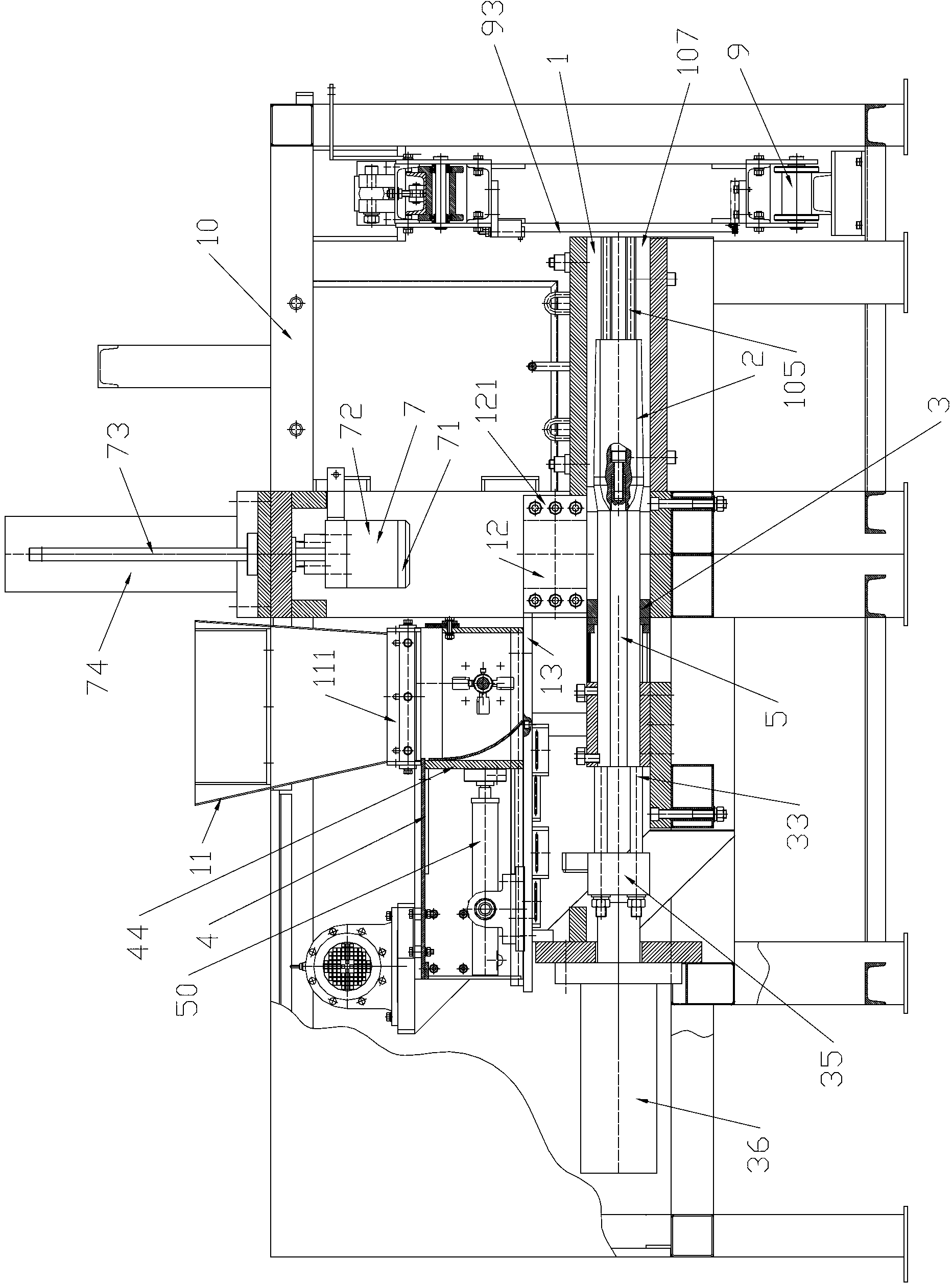
[0052] see figure 1 , 2 The hollow concrete slab continuous extruder shown includes an extrusion chamber 1, a mold core 2, a push plate device 3, a moving feeder device 4, a knife holder rod 5, a die pressing device 7, a wire cutting device 9, and a frame 10 , Hopper 11, feed bin 12, baffle plate 13.
[0053] The extrusion chamber 1 is a cuboid surrounded by four extrusion chamber plates 101 , the left end is an inlet 106 , and the right end is an outlet 107 . On the inner walls of the two opposing extruded bins 101, a side convex formwork 102 and a side concave formwork 103 are arranged. The side convex template 102 is provided with two parallel protrusions 104 extending to the exit of the extrusion bin, and the side concave template 103 is provided with two parallel concave portions 105 extending to the exit of the extrusion bin. The raised portion 104 is a corresponding tongue and groove structure.
[0054] The compression molding device 7 includes a compression molding...
Embodiment 2
[0078] Embodiment 2 is different from Embodiment 1 in that: the mold core is different, and the connection structure between the mold core and the knife holder rod is different. Specific instructions are given below.
[0079] In Embodiment 2, the right ends of the eight knife rest bars 5 are respectively connected to the left ends of the upper and lower three connecting plates 14, and there are 33 mold cores 8 (the mold cores on both sides of the middle horizontal plane are half mold cores, the One half of the mold core is connected with another horizontally adjacent mold core. Two half mold cores can be counted as a complete mold core), distributed on three horizontal planes, and two adjacent mold cores located on one horizontal plane The distance between the mold cores is equal, and the mold cores at different levels are staggered up and down. From the left end to the right end, the outer circumference of the cross-section of the mold core 8 gradually increases within the s...
PUM
 Abstract
Description
Claims
Application Information
 - R&D Engineer
- R&D Manager
- IP Professional
- Industry Leading Data Capabilities
- Powerful AI technology
- Patent DNA Extraction
Browse by: Latest US Patents, China's latest patents, Technical Efficacy Thesaurus, Application Domain, Technology Topic, Popular Technical Reports.
© 2024 PatSnap. All rights reserved.Legal|Privacy policy|Modern Slavery Act Transparency Statement|Sitemap|About US| Contact US: help@patsnap.com