Supercharge Your Innovation With Domain-Expert AI Agents!

Concave chambers of automotive rear tail lights

A technology of rear tail light and cavity, applied in the field of automobile body-in-white, can solve the problems of large matching gap between side wall outer panel and rear tail light, easy water leakage in the tail light area, affecting the appearance of the body grade, etc., so as to avoid stamping cracking and improve the The effect of body sealing and the effect of reducing the risk of deformation of the A side

Active Publication Date: 2013-08-07
CHERY AUTOMOBILE CO LTD
View PDF5 Cites 3 Cited by
  • Summary
  • Abstract
  • Description
  • Claims
  • Application Information

AI Technical Summary

Problems solved by technology

When welding the reinforcing plate, because the welding tongs are too close to the A side of the side wall outer panel (the outer surface of the side wall outer panel), it is easy to bump into the A side of the side wall outer panel, and the stress caused by welding will also directly cause the A side to crack. Deformation, reducing the quality of side A
Moreover, the welding seam between the flange and the reinforcing plate needs to be sealed by coating. If the sealing effect of the coating is not good, water leakage will easily occur in the taillight area
In order to avoid the above disadvantages, the rear taillight area can be directly drawn into an integral concave cavity structure, which is equivalent to making the flanging and reinforcing plate in the flanging structure into an integral structure, eliminating the welding process. Although the above problems have been overcome, since the depth of the cavity of the tail light is greater than 20mm, that is to say, the depth of the cavity is relatively deep, and cracking defects are prone to occur after drawing and shaping, and there is also a risk of deformation on the A surface, and the appearance of this structure The large radius of the characteristic fillet leads to a large matching gap between the side wall outer panel and the rear taillight, which directly affects the appearance of the vehicle and the body level

Method used


Image

  • Concave chambers of automotive rear tail lights
  • Concave chambers of automotive rear tail lights

Examples


Embodiment Construction

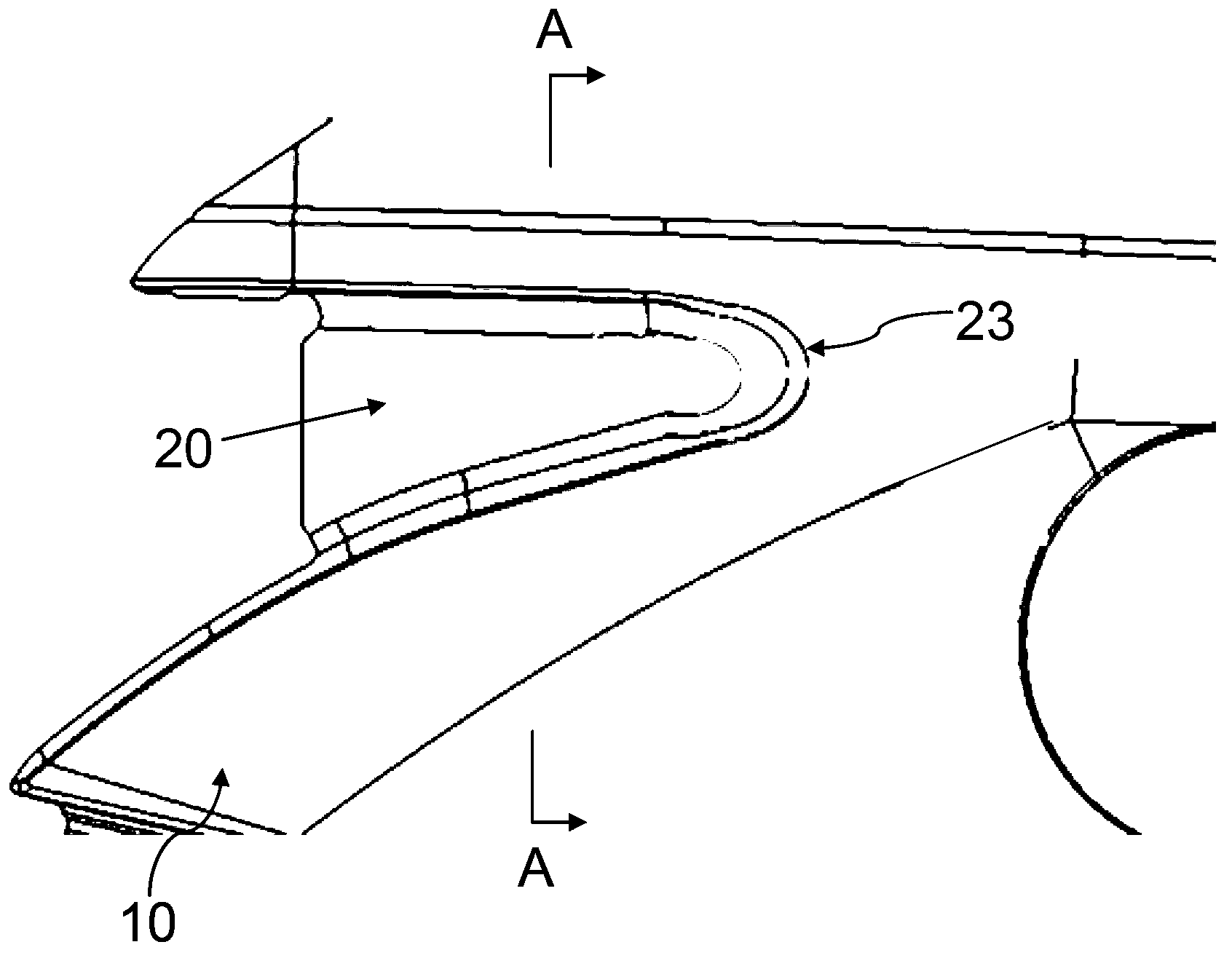
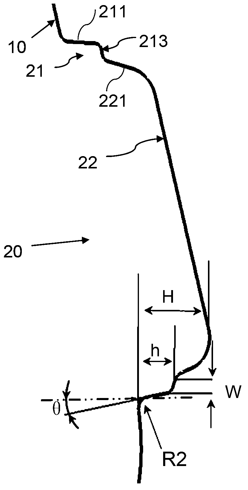
[0008] Such as figure 1 with 2 As shown, an automobile rear tail light cavity is characterized in that: the tail light area of ​​the side wall outer panel 10 is recessed toward the inner side of the vehicle body to form a cavity 20 for placing the rear tail light, and the cavity 20 is a flared stepped chamber , the concave cavity 20 includes a first concave cavity 21 and a second cavity 22, wherein the first concave cavity 21 is connected to the side wall outer panel 10, and the first side wall 211 on the first concave cavity 21 is connected to the side wall outer panel 10 Round corners are adopted for transition between them, and a stepped surface 213 is connected between the second side wall 212 and the first side wall 211 of the second concave cavity 22 .

[0009] The present invention can adopt following manufacturing method, and the steps are as follows:

[0010] a. The tail light area of ​​the side wall outer panel 10 is extended along the Y direction of the vehicle bo...


PUM


Abstract

The invention relates to the field of a body in white of an automobile, particularly to concave chambers of automotive rear tail lights. Tail light areas of a side frame outer panel are concaved towards the inner side of an automobile body to form into the concave chambers which are used for placing the automotive rear tail lights; the concave chambers which are flaring-shaped step chambers comprise a first concave chamber and a second concave chamber; the first concave chamber is connected with the side frame outer panel; a fillet is utilized to perform transition between a first lateral wall which is arranged on the first concave chamber and the side frame outer panel; and a step surface which is connected between a second lateral wall of the second concave chamber and the first lateral wall divides the concave chambers into two chambers with different deformation amplitudes. The tensile range of the first concave chamber is small, so that stamping and cracking of parts can be effectively avoided, deformation risks of an A surface are reduced, and the quality of the A surface of the side frame outer panel can be well guaranteed. The requirements of stamping processes can be met without the need for a large fillet radius between the first lateral wall of the first concave chamber and the side frame outer panel, so that the quality of the A surface of the side frame outer panel can be guaranteed, the installing and matching gaps can be reduced, and the level of the integral automobile body is improved.

Description

technical field [0001] The invention relates to the field of automobile body-in-white, in particular to an automobile rear tail light cavity. Background technique [0002] In the development process of vehicle body parts, the side panel takes a long time and costs a lot. Since there are many overlapping parts around the side panel, the quality of the product will directly affect the assembly and appearance clearance requirements of the vehicle. , especially the rear taillight area is more prone to problems. The cavity of the existing side wall outer panel for installing the rear taillight mostly adopts a flanging structure, and the flanging structure is punched out at the rear taillight area, and then a reinforcing plate is welded on the flanging. When welding the reinforcing plate, because the welding tongs are too close to the A side of the side wall outer panel (the outer surface of the side wall outer panel), it is easy to bump into the A side of the side wall outer pan...

Claims


Application Information

Patent Timeline
Patent Type & Authority Applications(China)
IPC IPC(8): B62D25/02
Inventor 贡见秀孟祥新
Owner CHERY AUTOMOBILE CO LTD
Features
  • R&D
  • Intellectual Property
  • Life Sciences
  • Materials
  • Tech Scout
  • Unparalleled Data Quality
  • Higher Quality Content
  • 60% Fewer Hallucinations
Learn More