Horizontal wheel rail gnawing preventing device for two-force rod system

A technology of two levers and horizontal wheels is applied in the field of horizontal wheel anti-gnawing rail devices, which can solve the problems of increasing maintenance costs, delaying production tasks, cumbersome assembly and disassembly methods, etc. The effect of mechanical influences

Inactive Publication Date: 2013-08-07
WUHAN UNIV OF SCI & TECH
View PDF5 Cites 6 Cited by
  • Summary
  • Abstract
  • Description
  • Claims
  • Application Information

AI Technical Summary

Problems solved by technology

(3) There is a gap between the horizontal guide wheel and the track. When the wheel wears to a certain extent, the gap must be readjusted. Howe

Method used


Image

  • Horizontal wheel rail gnawing preventing device for two-force rod system
  • Horizontal wheel rail gnawing preventing device for two-force rod system
  • Horizontal wheel rail gnawing preventing device for two-force rod system

Examples


Embodiment 1

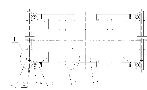
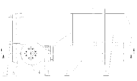
[0029] The utility model relates to a horizontal wheel anti-gnawing rail device of a two-force bar system. The device as figure 1 As shown, it includes four two-force link mechanisms, the fixed ends of the four two-force link mechanisms are symmetrically fixed on the four corners of the main girder 1 of the bridge frame, and the four two-force bar mechanisms are located on both sides of the main beam 1 of the bridge frame. Such as Figure 4 As shown, the installation gap e between the movable ends of the four two-force lever mechanisms and the inner side of the track 5 is 4-6mm. Such as figure 2 As shown, the stiffener plate is welded at the end of main beam 1 and the outer web.

[0030] The size and structure of the 4 two-force lever mechanisms are identical, and all consist of a fixed frame group and a horizontal wheel group.

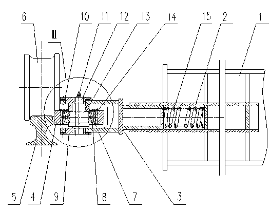
[0031] Such as image 3 As shown, the fixed frame set includes a box-shaped fixed frame 2 , a compression frame 3 and a compression spring ...

Embodiment 2

[0036] The utility model relates to a horizontal wheel anti-gnawing rail device of a two-force bar system. Except following technical parameter, all the other are with embodiment 1.

[0037] The installation clearance e between the movable ends of the four two-force rod mechanisms and the inner side of the track 5 is 6-8 mm; there are 5-8 radial oil holes on the wall of the stepped hole of the shaft sleeve 13; the eccentric transparent cover 9 is evenly arranged with 4 ~7 or 9~12 screw holes; the distance between the eccentric holes of the eccentric transparent cover 9 is b=20~25mm.

[0038] In this specific embodiment, during installation, the vertical centerline of the wheel 6 and the vertical centerline of the track 5 tend to be close to or even overlap, so as to balance the force couple and the reaction couple produced by the lateral force on the track 5 on both sides, and reduce the size of the lateral force on the rail. .

[0039] Compared with the prior art, this spec...


PUM


Abstract

The invention relates to a horizontal wheel rail gnawing preventing device for a two-force rod system. The technical scheme is as follows: the device comprises four two-force rod mechanisms with the same size and structure, and the four two-force rod mechanisms are symmetrically fixed on four corners of a bridge girder (1). Each two-force rod mechanism is composed of a fixed frame set and a horizontal wheel set, wherein the fixed frame set comprises a box-shaped fixed frame (2), a pressing frame (3) and a compression spring (15); the horizontal wheel set comprises a horizontal wheel (4), a bearing (8), an eccentric transparent cover (9), an adjustable pad (10), a wheel axle (12) and a shaft sleeve (13). The box-shaped fixed frame (2) is fixed on web plates at two sides of the bridge girder (1); the pressing frame (3) slides inside the box-shaped fixed frame (2) through the compression spring (15); and the horizontal wheel (4) is fixed on the pressing frame (3) through the bearing (8), the wheel axle (12) and the eccentric transparent cover (9). By using the horizontal wheel rail gnawing preventing device, the precise guide for the operation of a crane is realized; and a track (5) is in flexible contact with the horizontal wheel (4), thus the wheel rail gnawing phenomenon is effectively avoided. The horizontal wheel rail gnawing preventing device has the characteristics of simple structure, easiness for maintenance, strong stability and long service life.

Description

Technical field [0001] The present invention is the technology field of anti -rail device technology for crane operating agencies.Specifically involved a horizontal rotation device with a two -force rod system. Background technique [0002] The large -span bridge crane large -car running mechanism usually uses a two -wheel wheel. The function of the wheel edge is the horizontal side force of the orientation and bearing at the slope.When a heavy machine encounters problems such as "improper assembly position of the wheel assembly", "orbit height difference or parallel deviation", "bridge deformation" and other problems, it is easy to cause the wheels to run.The big impact will also cause severe wear, which is the phenomenon.According to the data, the phenomenon of rails occurred during the operation of bridge cranes is quite common, especially in the metallurgical industry with high loading work. Due to the rails caused by a large car wheel wheel, it accounts for about 85%of the t...

Claims


Application Information

Patent Timeline
IPC IPC(8): B66C9/16
Inventor 罗会信杨国华魏国前饶刚范勤康福
Owner WUHAN UNIV OF SCI & TECH
Why Eureka
Try Eureka