
Tee joint check valve

A through-stop, three-way technology, applied in multi-way valves, control valves, valve devices, etc., can solve the problems of tightness, loose valve core, etc., to simplify the pipeline, have good sealing performance, and save movable flanges and seals. circle effect

Inactive Publication Date: 2013-08-07
GUANGZHOU GOALAND ENERGY CONSERVATION TECH
View PDF7 Cites 2 Cited by
  • Summary
  • Abstract
  • Description
  • Claims
  • Application Information

AI Technical Summary

Problems solved by technology

[0003] The purpose of the present invention is to overcome the shortcomings of the above-mentioned prior art and provide a three-way check valve, which solves the problem of loose valve core and loose fit caused by welding.

Method used


Image

  • Tee joint check valve
  • Tee joint check valve
  • Tee joint check valve

Examples


Embodiment 1

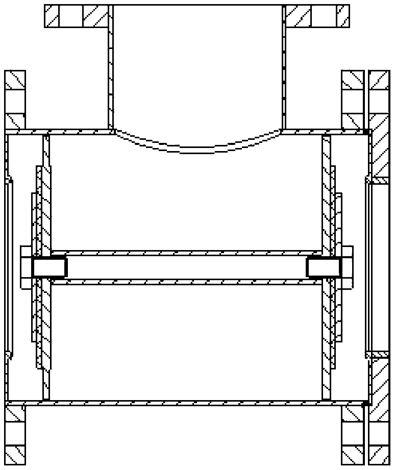
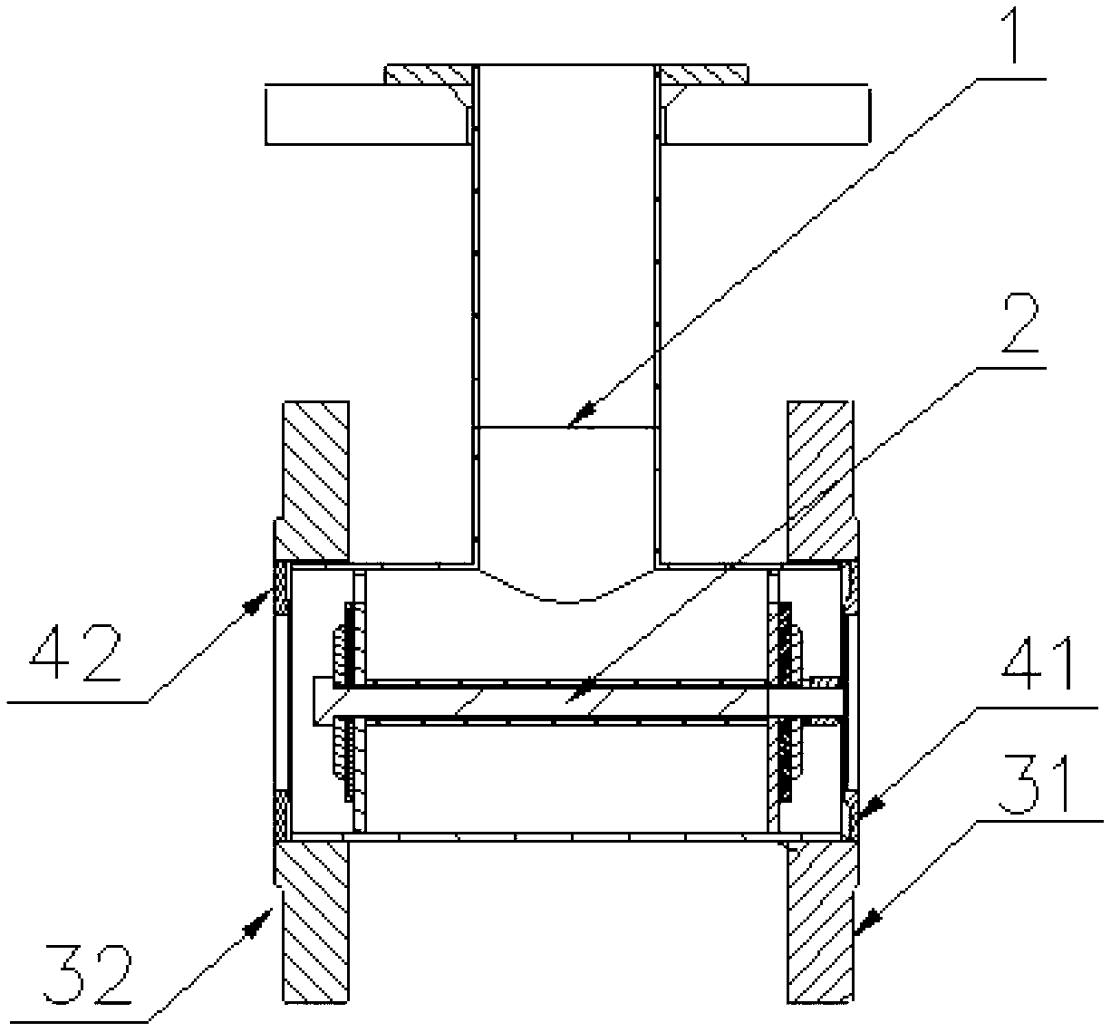
[0014] Such as figure 2 As shown, a three-way check valve includes a three-way base body 1, a movable valve core 2, flanges 3-1, 3-2 and sealing rings 4-1, 4-2, flanges 3-1 and 3 -2 are respectively connected to the two ends of the three-way base body 1 by welding, and form an annular groove matching the sealing retainer ring 4-1 and 4-2, the sealing retainer ring 4-1 and 4-2 are embedded in the annular groove, and the valve core is movable 2 is placed in the three-way base body 1, and can be engaged with the sealing retaining rings 4-1 and 4-2 to form a sealing surface to block the flow path.

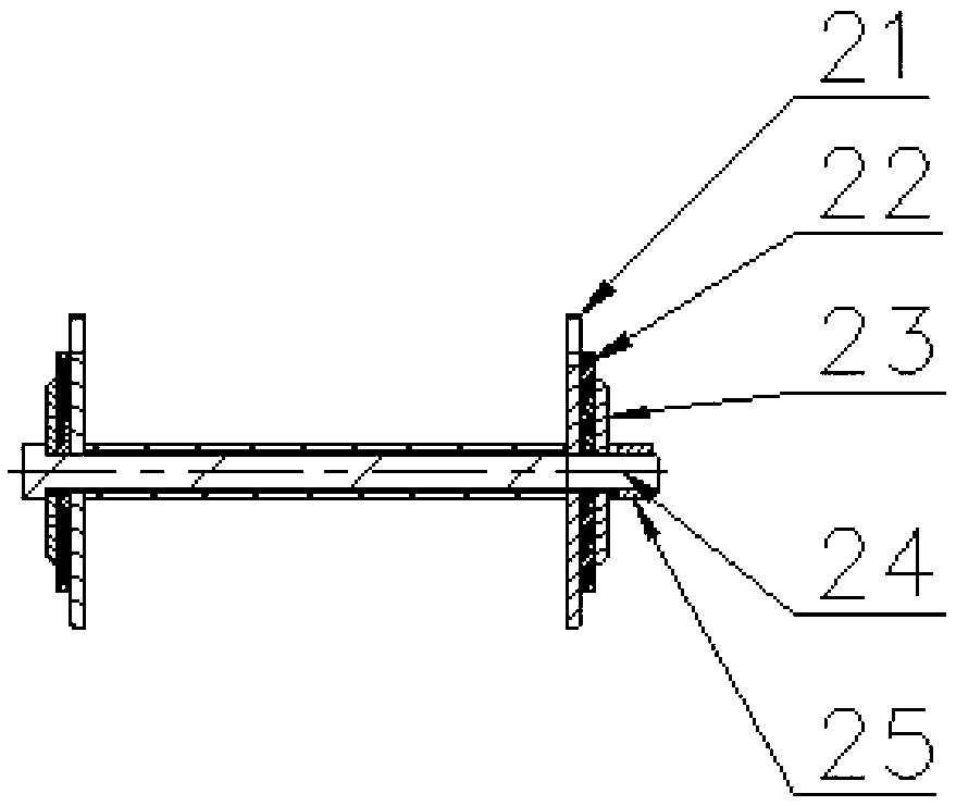
[0015] Such as image 3 The movable valve core 2 shown includes an I-shaped valve chip 21, a sealing ring 22, a pressure plate 23, a bolt 24, and a nut 25. The bolt 24 penetrates the I-shaped valve chip 21, the sealing ring 22 and the pressure plate 23, and is then fixed by a nut 25. The nut 25 Welded on the bolt 24.


PUM


Abstract

The invention discloses a tee joint check valve which comprises a tee joint basic body, a flexible valve core, flanges and a sealing retaining ring; the two flanges are respectively connected with two ends of the tee joint basic body in a welding mode to form into a circular groove which is matched with the sealing retaining ring; the sealing retaining ring is inserted into the circular groove; and the flexible valve core is embedded into the tee joint basic body and can be formed into a sealing surface with the sealing retaining ring in a meshing mode. Compared with the prior art, the tee joint check valve has the advantages of effectively avoiding metal deformation caused by welding due to the fact that the sealing retaining ring is inserted into the circular groove which is formed by the flanges and the tee joint basic body; being convenient to replace the flexible valve core and saving flexible flanges and sealing rings; and causing no looseness problem due to the fact that the flexible valve core is stable and reliable.

Description

Technical field [0001] The invention relates to a fluid check device, in particular to a three-way two-way check device. Background technique [0002] A double pump circulation system is often used in fluid transportation. For example, a closed circulating water cooling system for cooling high-power power electronic devices. In order to ensure the safe operation of high-power power electronic devices, the water cooling system is required to be absolutely reliable. The circulating water pump is the most critical component in the water cooling system, so two main circuits are generally configured The pumps, one for use and one for backup, form a double-pump circulation system. After a certain pump fails or runs for a certain period of time, it is switched to another pump. During the switching process, the cooling medium must be prevented from entering the shutdown pump. At present, the most commonly used method is to connect a check valve in series downstream of the two water pump...

Claims


Application Information

Patent Timeline
Patent Type & Authority Applications(China)
IPC IPC(8): F16K15/02F16K11/044
Inventor 冷明全文玉良李建军梁建源陈国华丘淼生
Owner GUANGZHOU GOALAND ENERGY CONSERVATION TECH
Learn More