
Rapid surface shape detection method for circular convex aspheric surfaces

A surface shape detection and aspheric technology, which is applied to measurement devices, instruments, optical devices, etc., can solve the problems of compensator detection, the impact of detection results is great, time-consuming, etc. The effect of obvious cost performance and broad market prospects

Inactive Publication Date: 2013-08-07
BEIJING INSTITUTE OF TECHNOLOGYGY
View PDF5 Cites 13 Cited by
  • Summary
  • Abstract
  • Description
  • Claims
  • Application Information

AI Technical Summary

Problems solved by technology

However, this detection method also has certain disadvantages. Specifically, it is necessary to design different compensators for aspheric elements with different surface shapes. Good correction of aspheric wavefront difference, on the other hand, requires reasonable allocation of tolerances such as thickness, curvature radius, air interval, and concentricity of each component of the compensator
Otherwise, the error of the compensator is very easy to produce ghost images, which will lead to the appearance of diffraction rings, and because the reflected light of some components of the compensator interferes with the reference light, some pseudo interference fringes appear on the image surface. Interference fringes and detection light are phase shifted at the same time, so it has a great influence on the detection results
The accuracy of the compensator is not only affected by the design results, but also by the installation and adjustment. The detection of the accuracy of the compensator itself is also a difficult problem
Compensation detection optical path adjustment is complicated and time-consuming

Method used


Image

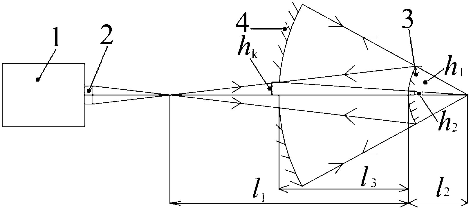
  • Rapid surface shape detection method for circular convex aspheric surfaces
  • Rapid surface shape detection method for circular convex aspheric surfaces
  • Rapid surface shape detection method for circular convex aspheric surfaces

Examples


Embodiment Construction

[0022] The specific implementation manner of the present invention will be described in further detail below in conjunction with the accompanying drawings.

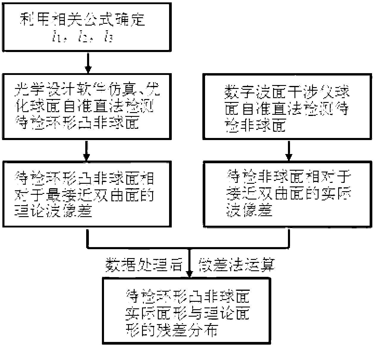
[0023] A rapid surface shape detection method for a circular convex aspheric surface. figure 1 It is a working principle diagram of the present invention.

[0024] According to the parameters of existing related components and equipment, calculate the parameters closest to the hyperboloid, and determine l 1 , l 2 and l 3 . For example, to detect a convex paraboloid with an effective light-passing diameter of Φ=8 to 100 mm, apex curvature radius r=236.2 mm, and eccentricity K=-1, there is a standard spherical mirror with a curvature radius R=557.01 mm, h k =22 mm, D=550 mm, calculated according to the above formula: h 1 = 4 mm, h 2 =50 mm, α=0.08, β=8.03, l 1 =830.42 mm, l 2 =103.42 mm, l 3 =464.96 mm, e=1.284, ie K=-1.649.

[0025] According to the above initial structural parameters, use optical design software...


PUM


Abstract

The invention discloses a rapid surface shape detection method for circular convex aspheric surfaces. The method includes: simulating wave aberration of a convex aspheric surface relative to a most approximate hyperbolic surface by optical design software based on a spherical surface auto-collimating method, fitting the wave aberration by Zernike polynomial under polar coordinates, and converting a wave aberration equation under the polar coordinates into an equation under rectangular coordinates; measuring the wave aberration of the aspheric surface relative to the hyperbolic surface by a digital wavefront interferometer, unifying a matrix of the actual wave aberration and a matrix of a theoretical wave aberration to the same coordinate system, allowing pixels in the two wave aberrations to be in one-to-one correspondence, and subjecting rise of the two wave aberrations to differential operation to obtain residual distribution of the actual surface shape and theoretical surface shape of the aspheric surface. Detection on the maximum asphericity and asphericity gradient of the aspherical surface by the method depends on the size and number of CCD (charge coupled device) array elements in the digital wavefront interferometer as well as the parameters of the selected most approximate hyperbolic surface. The method has the advantages of rapidity, accurateness, wide detection range and the like, and has promising market prospect.

Description

technical field [0001] The invention belongs to the technical fields of optical design and optical detection. technical background [0002] The equation for a toroidal aspheric surface can be expressed as In the formula, c is the curvature of the apex of the aspheric surface, K=-e 2 is the quadratic surface constant, a 1 , a 2 is the coefficient of the high-order term of the aspheric surface. The annular convex aspheric surface is only a part of the full-aperture convex aspheric surface (an annular area), and the inner ring is a blind area. [0003] The detection of the surface shape of high-precision optical aspheric components mainly adopts interference detection technology. In this technology, aberration-free point detection and zero compensation interference detection technology are widely used in surface shape detection in the aspheric polishing stage. [0004] Light travels from one point to another along a path with an extremum optical path, that is, light trav...

Claims


Application Information

Patent Timeline
IPC IPC(8): G01B11/24
Inventor 程灏波潘宝珠冯云鹏谭汉元丁仁强
Owner BEIJING INSTITUTE OF TECHNOLOGYGY
Learn More