Eureka AIR delivers breakthrough ideas for toughest innovation challenges, trusted by R&D personnel around the world.

L-shaped two-dimensional antenna array decoupling self-correcting and arrival direction estimating method

A technology for direction of arrival estimation and two-dimensional antennas, which is applied in antenna coupling, radio wave measurement systems, and directional devices for direction determination, etc., can solve the problems of high computational complexity and poor estimation effect, and achieve reduced computational complexity and simple implementation , Solve the effect of poor direction of arrival estimation accuracy

Inactive Publication Date: 2013-08-07
TIANJIN UNIVERSITY OF TECHNOLOGY
View PDF1 Cites 16 Cited by
  • Summary
  • Abstract
  • Description
  • Claims
  • Application Information

AI Technical Summary

Problems solved by technology

[0005] The purpose of the present invention is to overcome the disadvantages of the existing L-type two-dimensional antenna array decoupling self-correction and direction of arrival estimation under the condition of low signal-to-noise ratio, which have poor estimation effect and high computational complexity.

Method used


Image

  • L-shaped two-dimensional antenna array decoupling self-correcting and arrival direction estimating method
  • L-shaped two-dimensional antenna array decoupling self-correcting and arrival direction estimating method
  • L-shaped two-dimensional antenna array decoupling self-correcting and arrival direction estimating method

Examples


Embodiment Construction

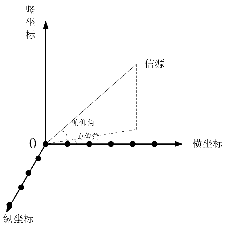
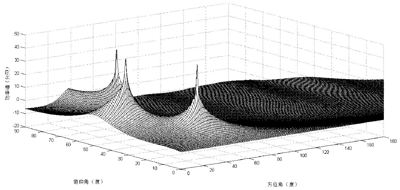
[0036] The following will refer to Figure 1-7 Specific embodiments of the present invention will be described.

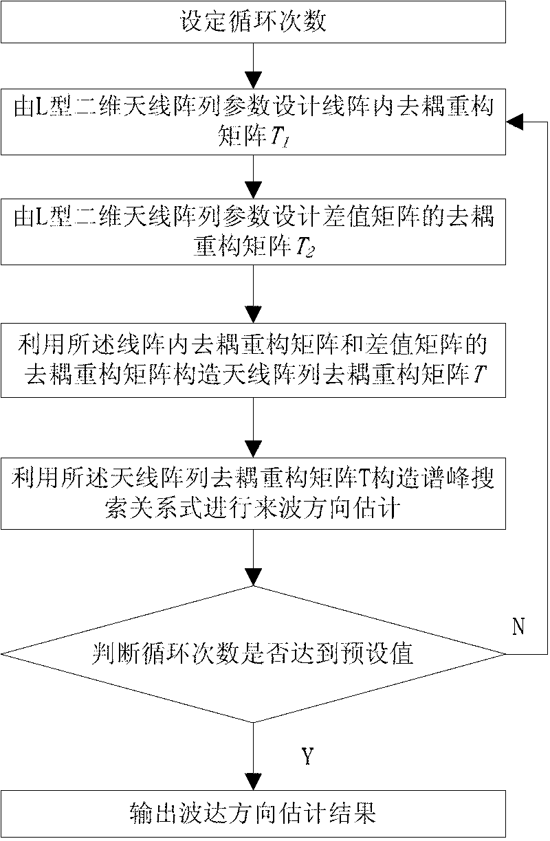
[0037] like figure 1 As shown, the method for performing L-shaped antenna array decoupling self-calibration in the embodiment of the present invention includes the following steps:

[0038] Step 1. Design the decoupling reconstruction matrix T in the linear array from the parameters of the L-shaped two-dimensional antenna array 1 , the decoupling reconstruction matrix T within the linear array 1 The expression is:

[0039]

[0040] β is the phase difference of adjacent array elements in the linear array, p is the mutual coupling degree of freedom in the linear array, M is the number of array elements contained in the linear array, and a is the steering vector of the received signal in the linear array matrix;

[0041] Wherein, the decoupling reconstruction matrix T in the linear array described in step 1 1 The determination methods specifically include:

...


PUM


Abstract

The invention discloses an L-shaped two-dimensional antenna array decoupling self-correcting and arrival direction estimating method, which comprises the following steps: designing a decoupling reconstructed matrix T1 in a linear array by an L-shaped two-dimensional antenna array parameter; designing a decoupling reconstructed matrix T2 of a difference value matrix by the L-shaped two-dimensional antenna array parameter; constructing an antenna array decoupling reconstructed matrix T by utilizing the decoupling reconstructed matrix in the linear array and the decoupling reconstructed matrix of the difference value matrix; constructing a spectral peak searching relational expression by utilizing the antenna array decoupling reconstructed matrix T, so as to estimate the arrival direction; and judging whether cycle times achieve a preset value, if not, repeating the above all steps, and if so, finishing decoupling self-correction and arrival direction estimation. With the adoption of the L-shaped two-dimensional antenna array decoupling self-correcting and arrival direction estimating method, the problems that the decoupling effect and arrival direction estimating precision are poor, and the operation quantity is higher are solved.

Description

technical field [0001] The present invention relates to antenna array decoupling and direction of arrival estimation technology, in particular to a method for decoupling self-calibration of L-shaped two-dimensional antenna array and estimation of direction of arrival Background technique [0002] The problem to be solved in the direction of arrival estimation is to locate the direction and angle of a certain wireless mobile source arriving at the smart antenna. At present, most direction of arrival estimates based on uniform antenna arrays are one-dimensional estimates, and this type of antenna can only estimate direction of arrival for one-dimensional angle information of sources in the range of 0° to 180°. Compared with the uniform antenna array, the L-shaped uniform antenna array can learn from the research results of the uniform linear array to estimate the direction of arrival of the two-dimensional angle information of the source in the range of 0° to 360°. However, d...

Claims


Application Information

Patent Timeline
Patent Type & Authority Applications(China)
IPC IPC(8): G01S3/46H01Q1/52
Inventor 马秀荣董旭皓
Owner TIANJIN UNIVERSITY OF TECHNOLOGY
Why Eureka
Eureka Blog
Learn More