Magnetic resonance radio-frequency subsystem and coil decoupling device and method thereof

A subsystem and decoupling technology, applied in the field of medical imaging, can solve problems affecting image quality, image signal-to-noise ratio reduction, decoupling performance reduction, etc.

Active Publication Date: 2018-04-06
GENERAL ELECTRIC CO
View PDF8 Cites 2 Cited by
  • Summary
  • Abstract
  • Description
  • Claims
  • Application Information

AI Technical Summary

Problems solved by technology

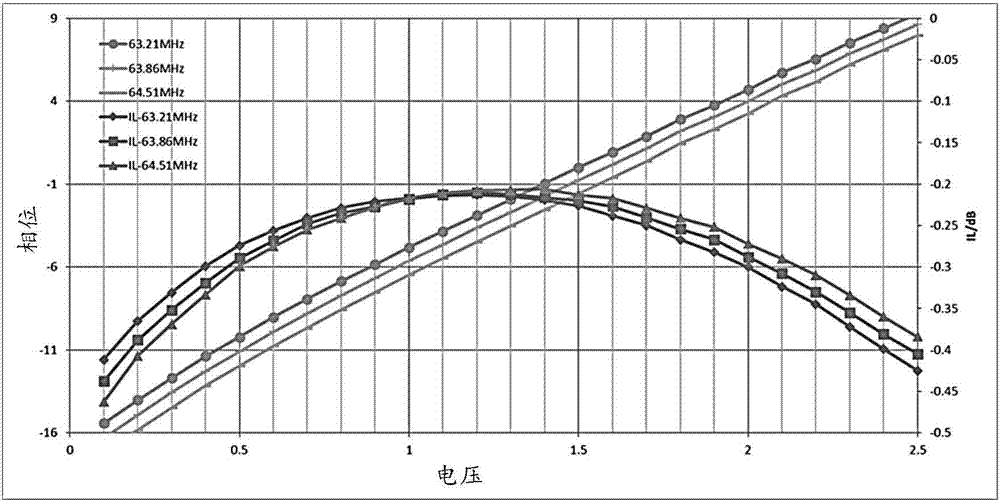
[0005] However, when scanning the patient, it is found that the decoupling performance of the body coil will be reduced due to the weight of the patient, which will reduce the image signal-to-noise ratio and affect the image quality

Method used


Image

  • Magnetic resonance radio-frequency subsystem and coil decoupling device and method thereof
  • Magnetic resonance radio-frequency subsystem and coil decoupling device and method thereof
  • Magnetic resonance radio-frequency subsystem and coil decoupling device and method thereof

Examples


Embodiment Construction

[0018] Specific implementations of the present invention will be described below. It should be noted that in the process of specific descriptions of these implementations, for the sake of concise description, it is impossible for this specification to describe all the features of the actual implementations in detail. It should be understood that, in the actual implementation process of any embodiment, just like in the process of any engineering project or design project, in order to achieve the developer's specific goals and to meet system-related or business-related constraints, Often a variety of specific decisions are made, and this can vary from one implementation to another. In addition, it will be appreciated that while such development efforts may be complex and lengthy, the technology disclosed in this disclosure will be Some design, manufacturing or production changes based on the content are just conventional technical means, and should not be interpreted as insuffic...


PUM


Abstract

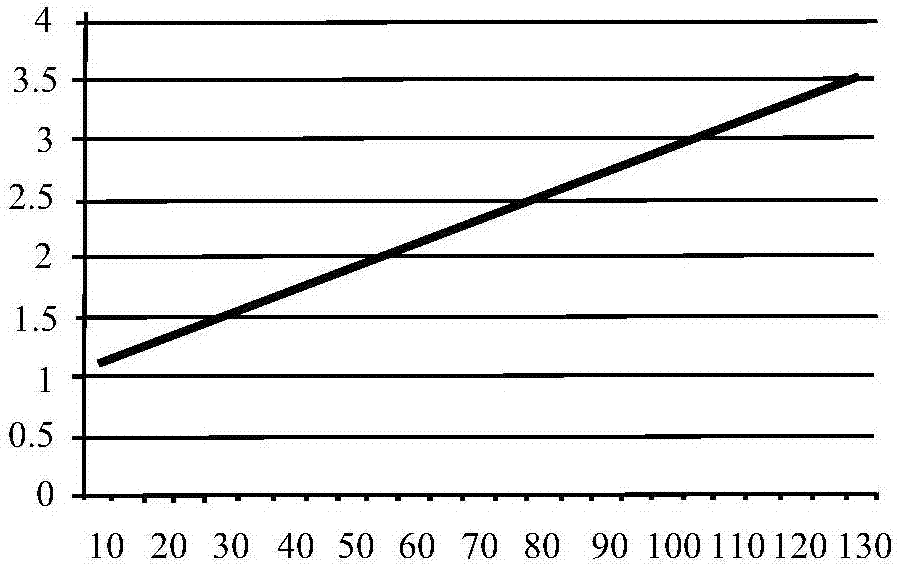
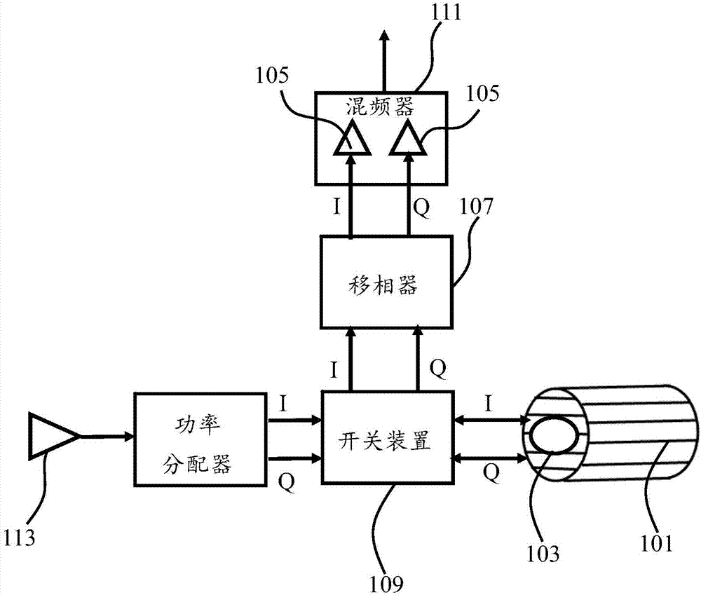
The invention provides a magnetic resonance radio-frequency subsystem and a coil decoupling device and method thereof. The magnetic resonance radio-frequency subsystem comprises a body coil, a surfacecoil and a preamplifier, wherein the body coil and the surface coil are used for receiving magnetic resonance signals, and the preamplifier is used for amplifying the magnetic resonance signals received by the body coil. The coil decoupling device comprises a phase shifter which is connected between the preamplifier and the body coil and used for receiving an external voltage regulation signal toregulate the working voltage, and the voltage regulation signal is determined according to the weight of a current patient.

Description

technical field [0001] The invention relates to the field of medical imaging, in particular to a magnetic resonance radio frequency subsystem and a coil decoupling device and method for it. Background technique [0002] A magnetic resonance system usually has a magnet subsystem, a radio frequency subsystem, a gradient subsystem, a signal acquisition subsystem, an image reconstruction subsystem, and a computer control subsystem. [0003] In the radio frequency subsystem of magnetic resonance, after the radio frequency excitation pulse is amplified by the radio frequency power amplifier, the I / Q dual-way switch is divided into I and Q two-way signals and transmitted to the body coil, and the body coil generates radio frequency excitation signals to excite the human body. Generate magnetic resonance signals. After the RF excitation is over, the I / Q dual switch switches from the transmitting mode to the receiving mode. In the receiving mode, the body coil can be used as a recei...

Claims


Application Information

Patent Timeline
Patent Type & Authority Applications(China)
IPC IPC(8): A61B5/055G01R33/36
CPCA61B5/055G01R33/3621G01R33/34076G01R33/3415G01R33/365G01R33/3657G01R33/3854G01R33/422G01R33/56
Inventor 邢昊洋戴擎宇刘渝肖春来仝晟汤伟男
Owner GENERAL ELECTRIC CO
Why Eureka
Try Eureka