Air conditioning device for vehicle

A technology for air-conditioning devices and vehicles, which is applied to vehicle parts, applications, household heating, etc. It can solve the problems of increasing the number of assembly operations and achieve the effects of suppressing temperature unevenness and driving torque

Active Publication Date: 2013-08-07
MAHLE INT GMBH
View PDF9 Cites 5 Cited by
  • Summary
  • Abstract
  • Description
  • Claims
  • Application Information

AI Technical Summary

Problems solved by technology

Therefore, the number of steps in the assembly

Method used


Image

  • Air conditioning device for vehicle
  • Air conditioning device for vehicle
  • Air conditioning device for vehicle

Examples


Embodiment Construction

[0051] Hereinafter, an embodiment of a vehicle air conditioner according to the present invention will be described with reference to the drawings. In addition, in the following drawings, in order to form each member into a recognizable size, the scale of each member may be appropriately changed.

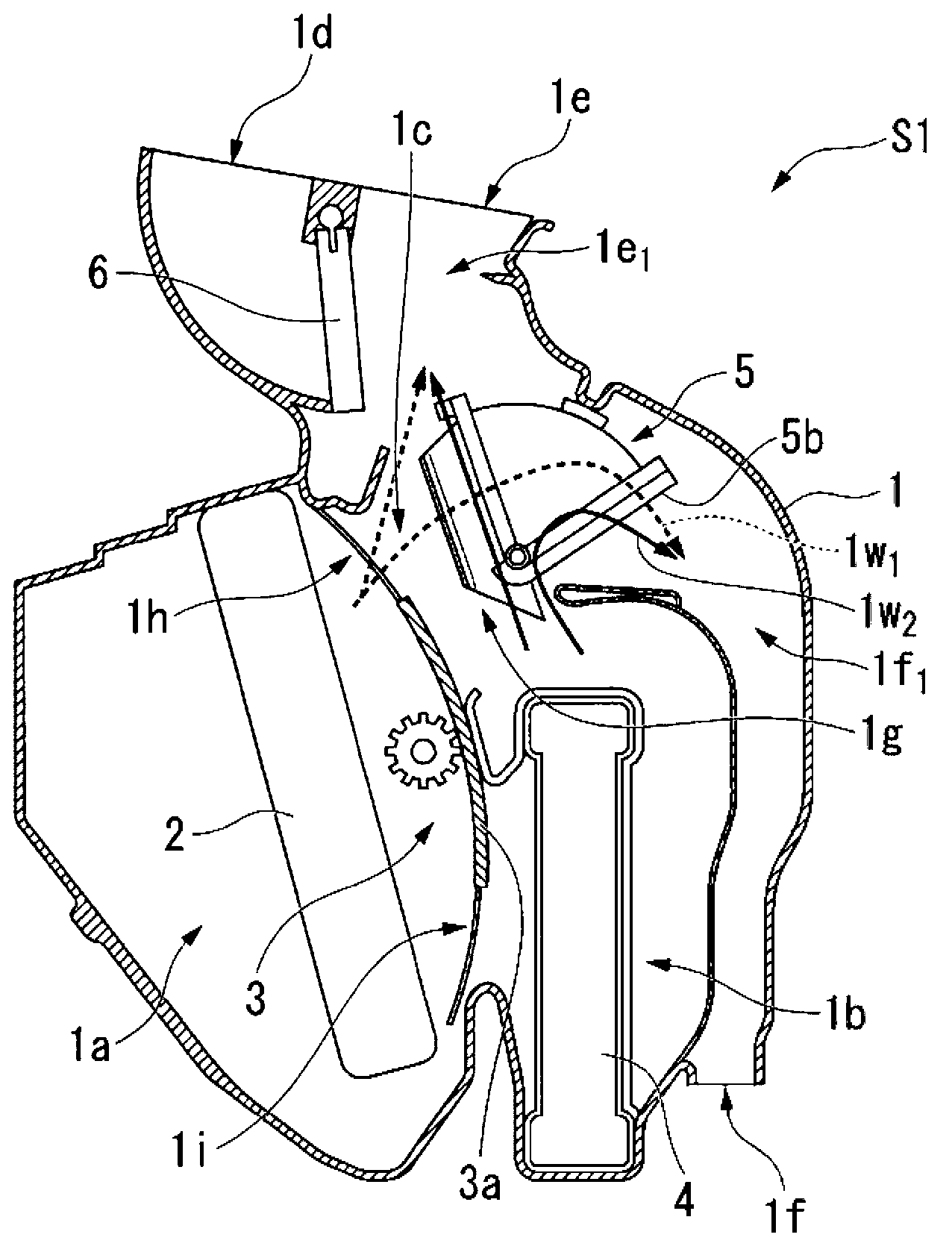
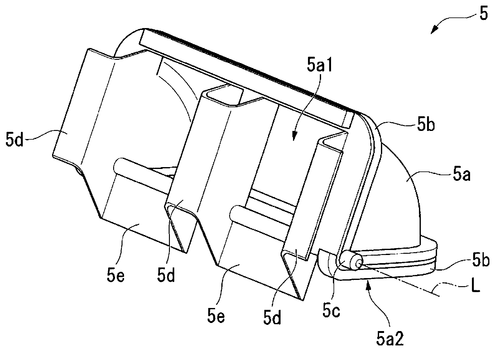
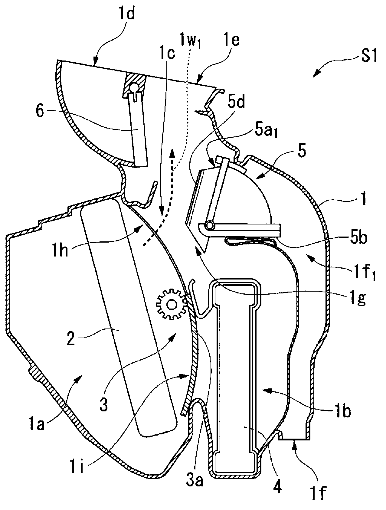
[0052] figure 1It is a sectional view showing a schematic configuration of a vehicle air conditioner S1 (HVAC: Heating Ventilation Air Conditioning) according to the present embodiment. As shown in the figure, the vehicle air conditioner S1 according to this embodiment has a casing 1, an evaporator 2, an air mixing damper 3, a heater core 4, a rotary damper 5 (air distribution damper), and a plate-shaped damper 6. .

[0053] The casing 1 has the outer shape of the vehicle air conditioner S1 of the present embodiment. In addition, a cooling flow path 1a in which the evaporator 2 is installed, a heating flow path 1b in which the heating core 4 is installed, and cold air (first airf...


PUM


Abstract

The present invention provides an air conditioning device for a vehicle, the air conditioning device comprising: a case which has therein a mixing region for mixing a first airflow and a second airflow and which also has a plurality of discharge openings connected to the mixing region and including a first discharge opening and a second discharge opening; and an airflow distribution adjusting damper adapted to be movable in the mixing region and adjusting the proportion of distribution of airflow to the first and second discharge openings depending on the position of the damper. The airflow distribution adjusting damper is provided with a guide path which leads a part of the second airflow to the first discharge opening without mixing the part of the second airflow with the first airflow. Therefore, the configuration can reduce a variation in the temperature of conditioning air without increasing the number of processes of work for assembling the air conditioning device for the vehicle and without involving an increase in the size of the air conditioning device for the vehicle.

Description

technical field [0001] The present invention relates to a vehicle air conditioner. [0002] This application claims priority based on Japanese Patent Application No. 2010-271945 for which it applied in Japan on December 6, 2010, and uses the content here. Background technique [0003] Generally, in a vehicle air conditioner, supplied air is cooled by an evaporator to form cold air. Then, conditioned air is generated by adjusting the heating ratio of the cold air. [0004] More specifically, the vehicle air conditioner includes a case having an outer shape and having a flow path formed therein. In addition, the inside of the casing is branched into two flow paths, and a heater core is provided in the flow paths. Furthermore, in the vehicle air conditioner, the heating ratio of the cold air is adjusted by adjusting the supply amount of the cold air to the flow path provided with the heating core. [0005] However, since the air conditioner for a vehicle needs to be install...

Claims


Application Information

Patent Timeline
IPC IPC(8): B60H1/00B60H1/12
CPCB60H1/00685F24F2013/1446B60H2001/00721
Inventor 贝山浩一
Owner MAHLE INT GMBH
Why Eureka
Try Eureka