Gear unit with improved lubricant supply

a technology of lubricant supply and gear unit, which is applied in the direction of gearing details, machines/engines, mechanical apparatus, etc., can solve the problems of mechanical lubricant pump frequently not being able to accommodate compactly designed gear units, affecting the performance of gear units, and affecting the operation of gear units. , to achieve the effect of reducing the power requirement, reducing the delivery rate and reducing the power consumption

Inactive Publication Date: 2013-05-30
SIEMENS AG
View PDF13 Cites 31 Cited by
  • Summary
  • Abstract
  • Description
  • Claims
  • Application Information

AI Technical Summary

Benefits of technology

[0008]A gear unit according to the present invention is applicable for industrial applications or wind turbines with a lubricant supply system which in all operating states of a drive system comprising the gear unit permits a reliable supply of lubricant and has a reduced energy requirement, in particular in the event of a sudden power failure or in spinning operation. The gear unit has an optimized lubricant supply system in respect of its power needs. By ensuring a splash lubrication level in the lubricant sump in emergency or spinning operation a reliable supply of lubricant is guaranteed at all times, in particular in the event of a sudden power failure. Advantageously, the dry sump level in the lubricant sump is below all gear wheels of the inventive gear unit.
[0010]According to another advantageous feature of the present invention, the control unit can be configured to control the level in the lubricant sump exclusively by adjusting a delivery rate of the lubricant pump. This permits a particularly simple implementation of a gear unit according to the present invention on the basis of existing designs. If the lubricant pump is for example set to full delivery rate in normal operation, the control unit for adjusting the level can be implemented particularly easily.
[0012]According to another advantageous feature of the present invention, the lubricant collection container can be connected to a lubricant feed point for the bearing or gear wheel arranged above the lubricant sump via a pipe connection or a lubricant supply channel integrated into the gear unit housing. In this way, even bearings and gear wheels arranged above the splash lubrication level can always be reliably supplied with lubricant in emergency or spinning operation.
[0013]According to another advantageous feature of the present invention, the control unit can be configured to adjust the level in the lubricant sump to a splash lubrication level in part-load operation, with the lubricant pump being set in the part-load operation to a reduced delivery rate for transporting lubricant to the at least one lubricant feed point. This permits a further reduction in the power needs for the lubricant supply system of the inventive gear unit.
[0014]According to another advantageous feature of the present invention, the lubricant compensating reservoir can be separated in part-load operation from the lubricant tank and from the at least one lubricant feed point by an actuating element or passive switch element. A splash lubrication level can thereby easily be implemented in the lubricant sump during part-load operation.

Problems solved by technology

Particularly in permanent operation or where there are a large number of load changes, gear units are subject to considerable fatigue stresses in the form of overrollings.
Even though lubricant pumps permit a satisfactory pumping volume even at low speeds, they are subject to extreme stress in a nominal output range of the gear unit and are appreciably overdimensioned for a lower speed range.
Furthermore, mechanical lubricant pumps frequently cannot be accommodated in compactly designed gear units because of the space they require.

Method used


Image

  • Gear unit with improved lubricant supply
  • Gear unit with improved lubricant supply
  • Gear unit with improved lubricant supply

Examples


Embodiment Construction

[0022]Throughout all the figures, same or corresponding elements may generally be indicated by same reference numerals. These depicted embodiments are to be understood as illustrative of the invention and not as limiting in any way. It should also be understood that the figures are not necessarily to scale and that the embodiments are sometimes illustrated by graphic symbols, phantom lines, diagrammatic representations and fragmentary views. In certain instances, details which are not necessary for an understanding of the present invention or which render other details difficult to perceive may have been omitted.

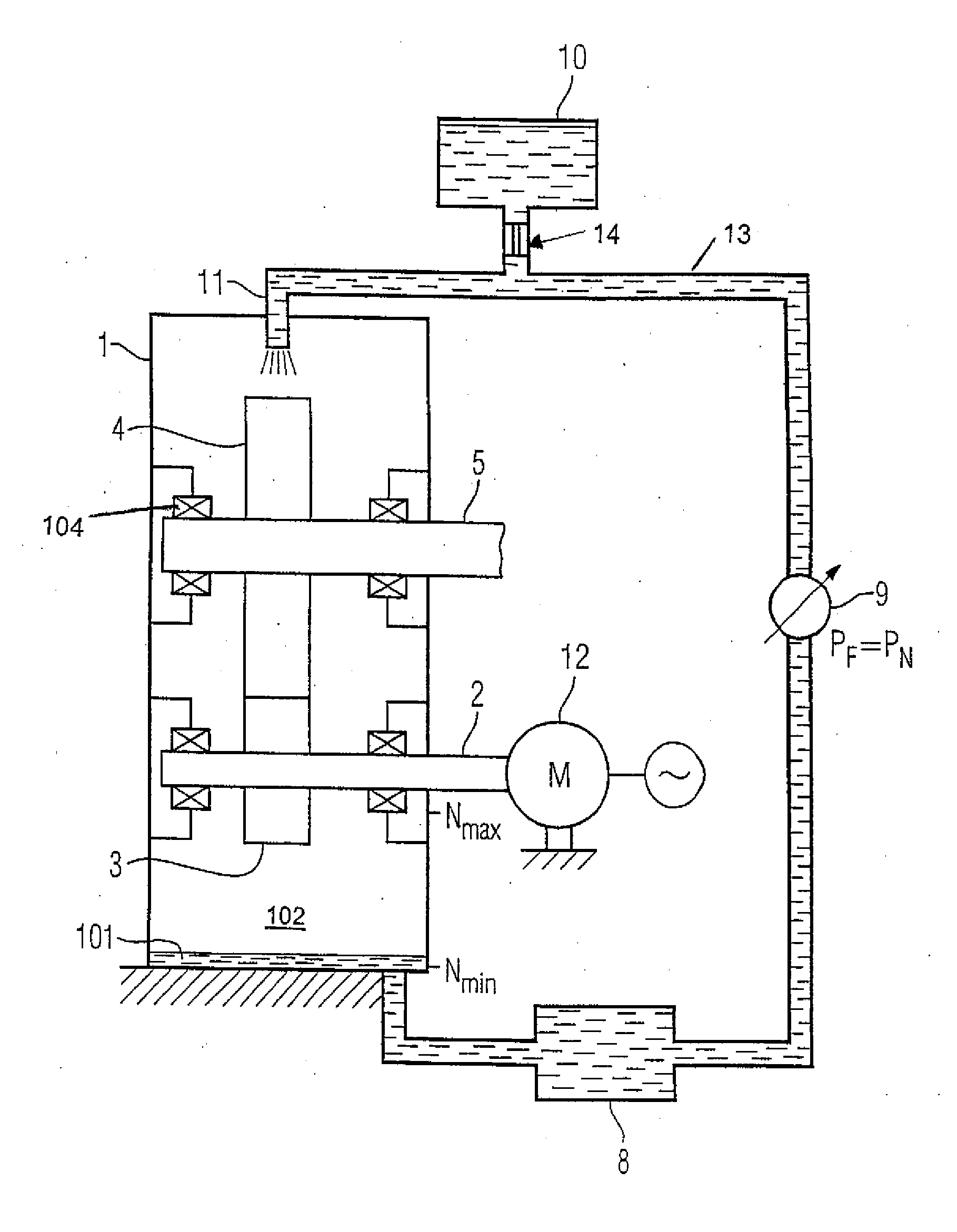
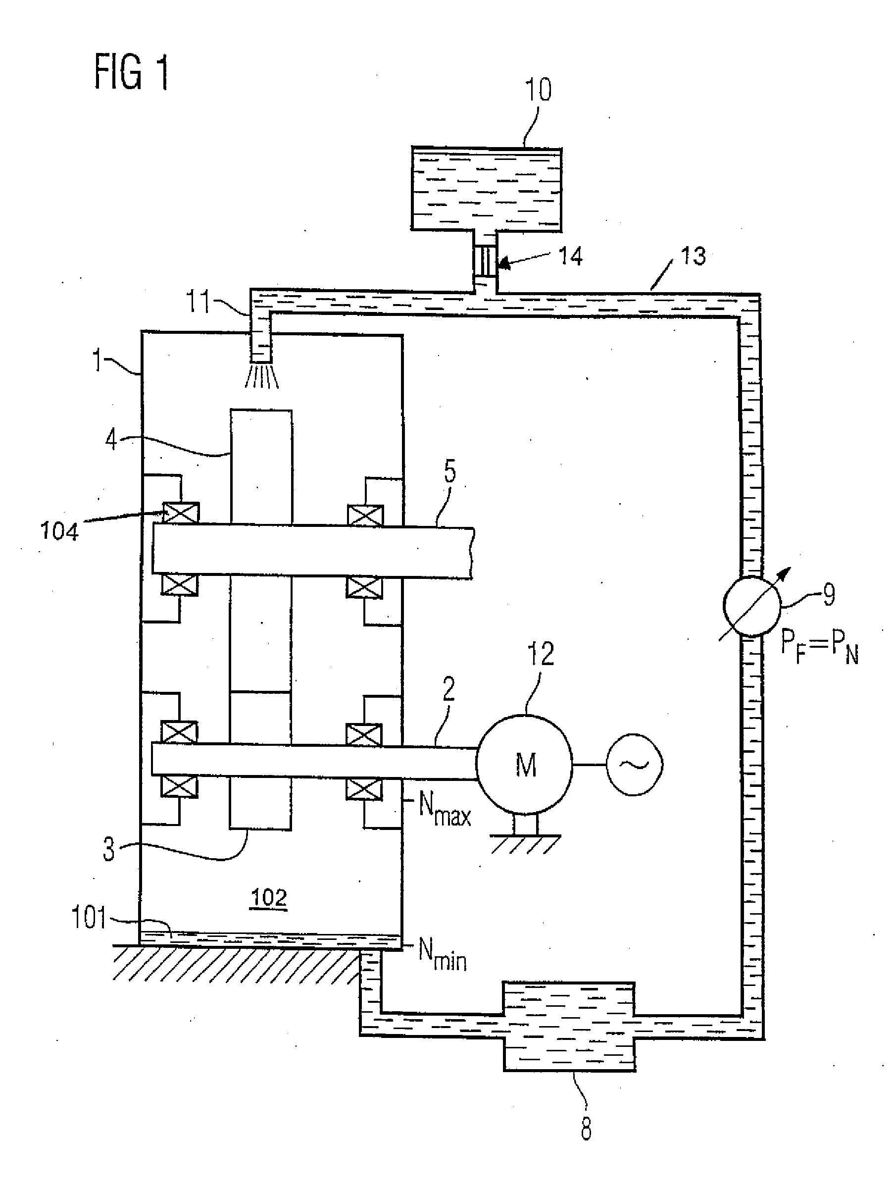
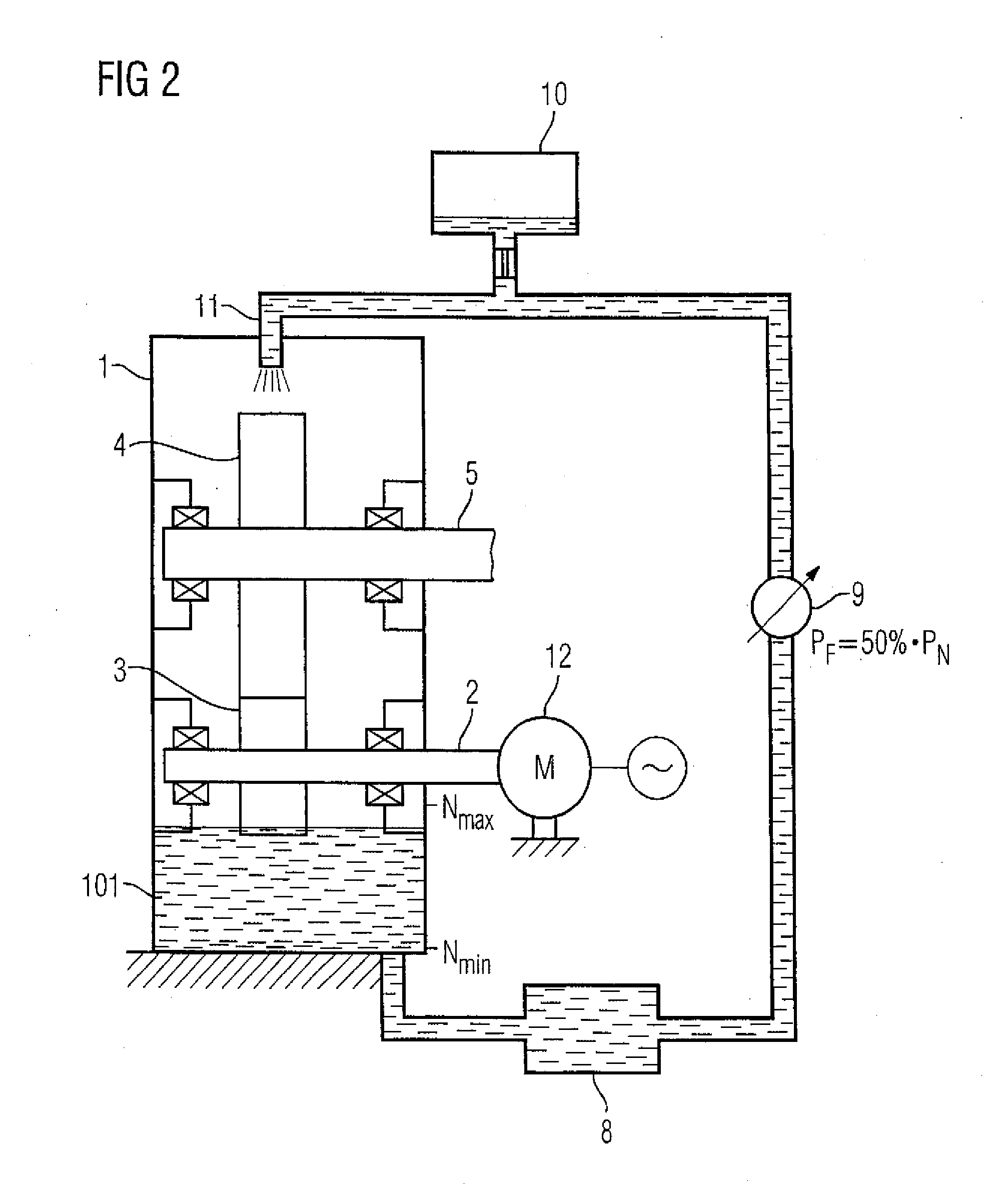
[0023]Turning now to the drawing, and in particular to FIG. 1, there is shown a schematic illustration of a gear unit according to the present invention. The gear unit has a gear unit housing 1 and two spur gears 3, 4 which are accommodated in the gear unit housing 1 and engage with one another. A drive shaft 2 and an output shaft 5 which are mounted in the gear unit housing...


PUM


Abstract

In order to implement a reliable supply of lubricant to gear unit components during emergency or spinning operation of a gear unit, level control is provided in a lubricant sump of the gear unit as a function of the operating state by means of a control unit associated with a lubricant pump. During normal operation the level is adjusted to dry sump level. In contrast, the lubricant pump is switched off in emergency or spinning operation, so that a splash lubrication level is automatically achieved in the lubricant sump.

Description

CROSS-REFERENCES TO RELATED APPLICATIONS[0001]This application claims the priority of European Patent Application, Serial No. EP 11 191 335.6, filed Nov. 30, 2011, pursuant to 35 U.S.C. 119(a)-(d), the content of which is incorporated herein by reference in its entirety as if fully set forth herein.BACKGROUND OF THE INVENTION[0002]The present invention relates to a gear unit for industrial applications or wind turbines.[0003]The following discussion of related art is provided to assist the reader in understanding the advantages of the invention, and is not to be construed as an admission that this related art is prior art to this invention.[0004]In gear units for industrial applications or wind turbines an adequate supply of lubricant to sliding or rolling contacts of bearings, shafts, bolts, running gears or spline gears must be ensured under all operating conditions. Particularly in permanent operation or where there are a large number of load changes, gear units are subject to co...

Claims


Application Information

Patent Timeline
Patent Type & Authority Applications(United States)
IPC IPC(8): F16H57/04
CPCF16H57/0447F03D11/0008F16H57/0423F16H57/045Y10T74/19995F16H57/0457F16H57/0495F16N7/40F16H57/0456F03D80/70Y02E10/72F01M1/02F01M11/0004F16H57/0442
Inventor BARTHEL, THOMASREIMERS, JAN-DIRKTEBROKE, JORGWEINSDORFER, ULRICH
Owner SIEMENS AG
Why Eureka
Try Eureka