Device for loading a shaft furnace

a technology for shaft furnaces and furnaces, applied in vertical furnaces, furnaces, lighting and heating apparatuses, etc., can solve problems such as inaccuracy of rotor centring, and achieve the effect of easy replacement and easy integration

Inactive Publication Date: 2004-11-11
PAUL WURTH SA
View PDF4 Cites 33 Cited by
  • Summary
  • Abstract
  • Description
  • Claims
  • Application Information

AI Technical Summary

Benefits of technology

0010] It should be recalled first of all that the loading device according to the invention is of the type which consists of a housing mounted at the top of a shaft furnace, a suspension rotor suspended in that housing in such a way that it can rotate, a loading chute suspended in the suspension rotor and at least one cooling circuit supported by the suspension rotor. This cooling circuit is fed by a liquid coolant through a rotating annular joint which is of the type consisting of: a fixed ring mounted in the housing, a rotating ring rotating with the suspension rotor and bearings between the fixed and rotating rings. In this rotating joint, the fixed and rotating rings together form a cylindrical interface in which one or more annular grooves transfer a pressurised liquid coolant between the fixed and rotating rings. The transfer of the liquid coolant from the rotating ring to the suspension rotor is then effected by connections between the rotating ring and suspension rotor. The device according to the invention is distinguished in particular by the characteristics which will be explained below. The rotating annular joint is mounted on the inside of the housing, in an annular tank for collecting leaks which is formed by the suspension rotor. Furthermore, the rotating ring of this rotating joint is mounted solely on the fixed ring by means of bearings. Selective coupling means couple this rotating ring, floating on the fixed ring, with the suspension rotor in such a way as to transmit the rotational motion of the suspension rotor to the rotating ring selectively, while at the same time preventing other forces from being transmitted from the suspension rotor to the rotating ring. Lastly, the connection means include a deformable tubular section, such that these connection means form a non-rigid connection between the rotating ring and the suspension rotor. It will be appreciated that, finally after twenty years, these characteristics provide a reliable solution to supplying rotating equipment of a loading device for a shaft furnace with pressurised liquid coolant. Indeed, in the solution according to the invention, the rotating joint does not cause any problems of leakage or of excessive friction, nor any problems with the life expectancy of the watertight fittings nor any problems of differential thermal expansion or problems of seizure. The rotating joint is not susceptible to the violent shocks that are inevitably absorbed by the suspension rotor holding the chute. Nor is it susceptible to rotor centring inaccuracies and variations in the plate of rotation of the suspension rotor. No special machining is required for the suspension rotor of the chute. The rotating joint can be replaced easily without removing the suspension rotor.
0011] It will also be appreciated that the device according to the invention enables a cooling circuit supported by the suspension rotor to be integrated easily in a closed cooling circuit. To this end, it is sufficient to provide a first annular groove in the cylindrical interface to transfer liquid coolant from the fixed ring to the rotating ring, and a second annular groove in the cylindrical interface to transfer liquid coolant from the rotating ring to the fixed ring. This enables liquid coolant to pass back and forth through the rotating annular joint.

Problems solved by technology

Nor is it susceptible to rotor centring inaccuracies and variations in the plate of rotation of the suspension rotor.

Method used


Image

  • Device for loading a shaft furnace
  • Device for loading a shaft furnace
  • Device for loading a shaft furnace

Examples


Embodiment Construction

[0026] In the figures shown, item numbers which are the same indicate components which are similar or identical.

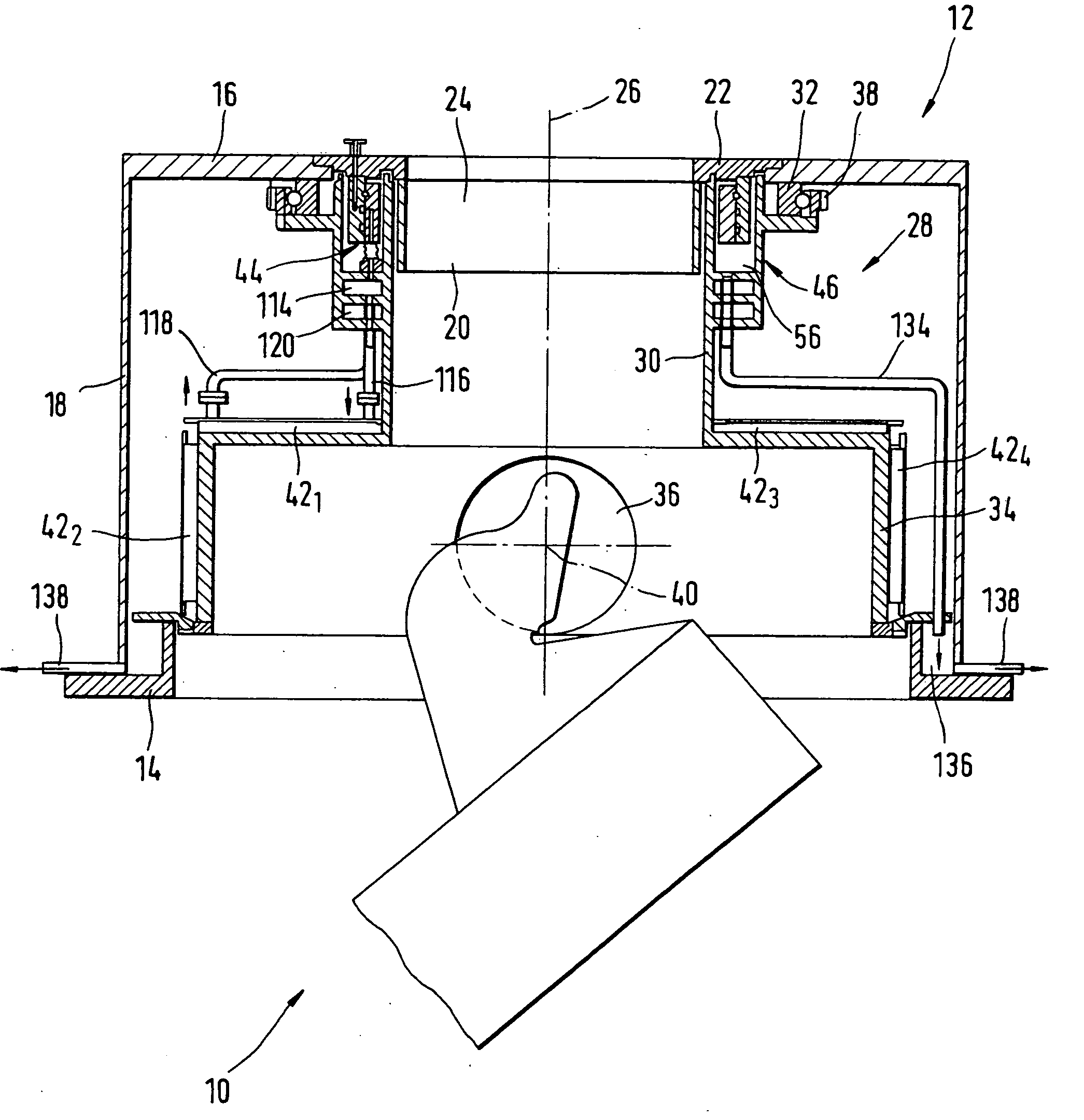
[0027] FIG. 1 shows a loading device with a rotating chute 10, designed to be mounted on a shaft furnace, such as a blast furnace, in diagrammatic form.

[0028] This device consists of a housing 12 with an annular flange 14 at the bottom, a support plate 16 at the top and a side wall 18. The annular flange 14 connects the housing 12 to a mating flange (not shown) of a shaft furnace, to produce a watertight joint. The support plate 16 is connected to the bottom of a hopper or gate housing (not shown). Side wall 18 provides a watertight connection between flange 14 and supporting plate 16. A fixed feed sleeve 20 is mounted in a central opening of the support plate 16 by means of an annular flange 22. This fixed feed sleeve 20 extends into housing 12 to define a feed channel 24 for the material to be loaded into the shaft furnace. This feed channel 24 has a central axis 26 whic...


PUM

PropertyMeasurementUnit
forcesaaaaaaaaaa
flexibleaaaaaaaaaa
thermal expansionaaaaaaaaaa

Abstract

A loading device for a shaft furnace comprises a chute supported by a suspension rotor (28) in a fixed housing. The rotor (28) is fitted with a cooling circuit, supplied with liquid coolant via a rotating annular joint (44). The latter comprises a fixed ring (60) and a rotating ring (62), and is fitted in an annular leak collecting tank (46) formed by the suspension rotor (28). Fixed ring (60) is supported by the housing (12). Rotating ring (62) is supported entirely by fixed ring (60) via a bearing (64). Selective coupling means (65, 66) connect the rotating ring (62) to the suspension rotor (28) in such a way as to transmit a rotary moment of rotor (28) to rotating ring (62) selectively, while at the same time preventing other forces from rotor (28) being transmitted to rotating ring (62).

Description

[0001] The present invention concerns a loading device for a shaft furnace. More particularly, it concerns the cooling of a loading device for a shaft furnace, such as a blast furnace, comprising a housing to be mounted at the top of the shaft furnace, a suspension rotor suspended in such a way that it rotates on that housing, a loading chute suspended in the suspension rotor and at least one cooling circuit supported by the suspension rotor.PRIOR ART[0002] In 1978, the company Paul Wurth S. A. proposed such a loading device, which is described in detail in U.S. Pat. No. 4,273,492. The suspension rotor in this device is fitted with a lower protective screen which surrounds the chute feed channel and protects the drive means mounted in the housing against the radiant heat from the inside of the shaft furnace in particular. To this end, the lower screen contains a cooling circuit which is supplied with liquid coolant via a rotating annular connection around the chute feed channel. Thi...

Claims


Application Information

Patent Timeline
Patent Type & Authority Applications(United States)
IPC IPC(8): C21B7/20F27B1/20
CPCC21B7/20
Inventor LONARDI, EMILECIMENTI, GIOVANNI
Owner PAUL WURTH SA
Why Eureka
Try Eureka