Gearbox for a rail vehicle drive train

A rail vehicle and transmission technology, applied in the field of rail vehicles, can solve the problems of increasing transmission and spare parts manufacturing- and storage costs, limiting transmission applications, etc.

Inactive Publication Date: 2013-08-07
VOITH PATENT GMBH
View PDF9 Cites 5 Cited by
  • Summary
  • Abstract
  • Description
  • Claims
  • Application Information

AI Technical Summary

Problems solved by technology

Manufacturers of such rail vehicle transmissions therefore usually offer various transmissions of different sizes, which greatly limits the use of the same type of components for various sizes of transmissions
This increases manufacturing - and storage costs for new transmissions and spare parts
In addition, the available transmission ratios are limited by the specified ground clearance of the rail vehicle, which varies depending on the diameter of the gear used.

Method used


Image

  • Gearbox for a rail vehicle drive train
  • Gearbox for a rail vehicle drive train

Examples


Embodiment Construction

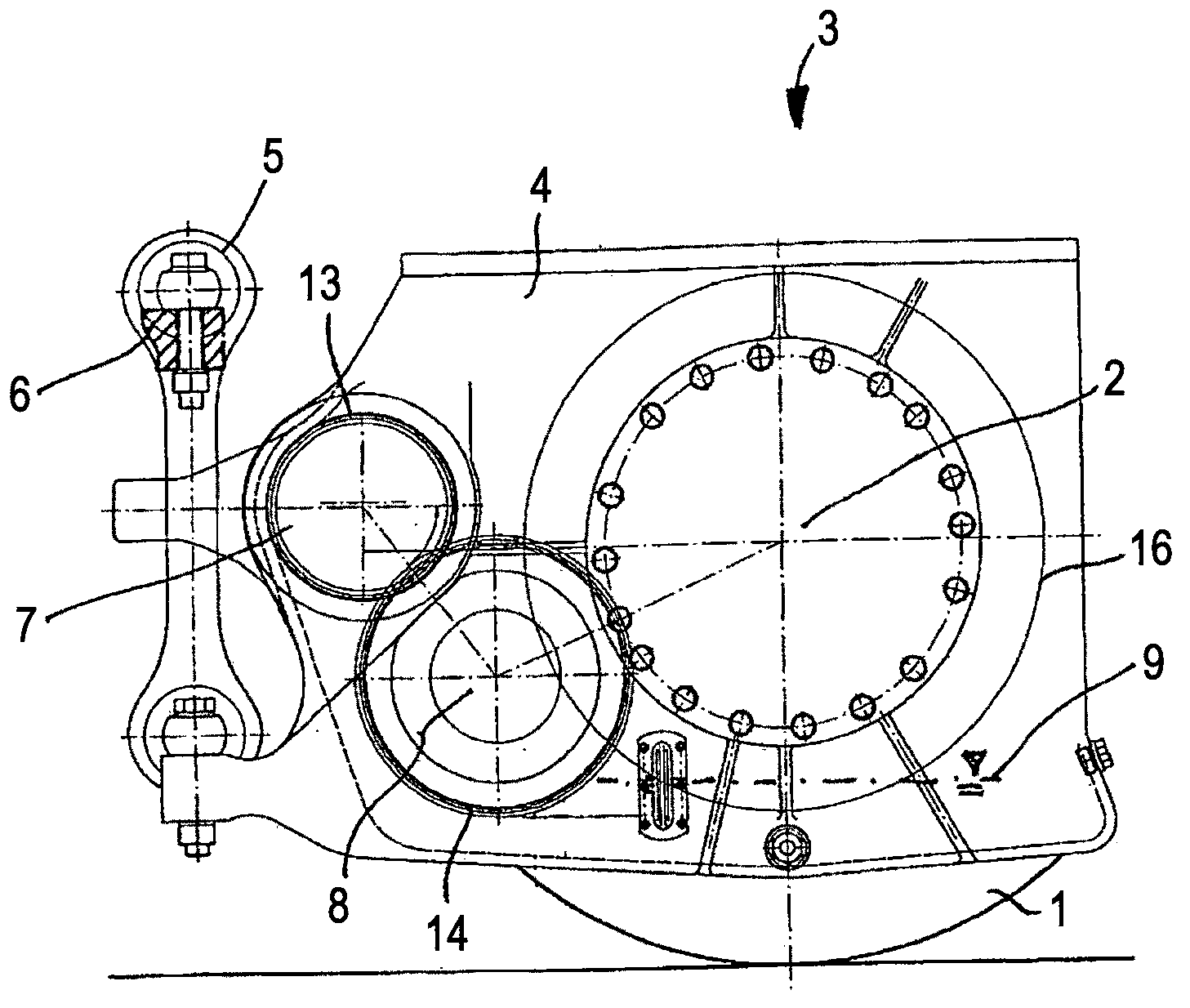
[0027] exist figure 1 A drive wheel 1 of a rail vehicle is shown in . Drive wheels 1 are supported by an output shaft 2 of a transmission 3 . The transmission 3 itself, including the transmission housing 4 , is mounted on the output shaft 2 and is supported against torsion by means of a torque bearing 5 on a bogie 6 (here only a small part is shown shaded).

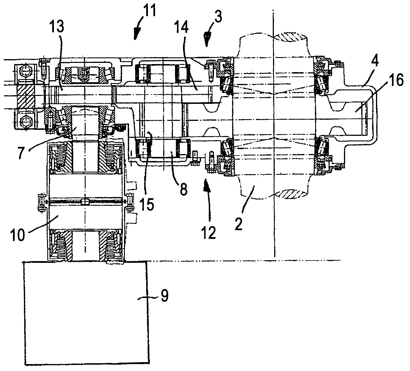
[0028] drive engine (in figure 1 (not shown in ) is introduced into the transmission 3 through the input shaft 7 of the transmission 3 . The drive power is transmitted from the input shaft 7 to the output shaft 2 through the intermediate shaft 8 by means of two gear pairs, according to the following figure 2 Detail the gear pair.

[0029] In the transmission housing 4, an oil sump 9 is formed in the lower region, by means of which the transmission is lubricated and at least the driven gear 16 on the output shaft 2 and the gear on the intermediate shaft 8 meshing with it and the intermediate The gear wheel 14 of the ...


PUM


Abstract

The invention concerns a transmission for the drive train of a rail vehicle having an input for connecting a drive motor of the rail vehicle; having an output for connecting the drive wheels of the rail vehicle; having a drive connection between the input and the output which forms a transmission ratio between 5 and 10. The invention is characterised in that the transmission ratio is formed by two transmission stages connected between one another in the drive connection, from which the first transmission stage has a transmission ratio between 1 and 2 and the second transmission stage connected downstream in the drive power flow after the first transmission stage from the input to the output has a transmission ratio of more than double the first transmission stage.

Description

technical field [0001] The invention relates to a transmission for a drive train of a rail vehicle, in particular according to the preamble of claim 1 . The invention is particularly suitable for rail vehicles in short-distance rail traffic, which have a maximum operating speed of 80 to 110 km / h, and in particular rail vehicles in underground rail transit (metro). Background technique [0002] Single-stage spur gear transmissions are usually used in metro-rail vehicles to transmit the drive power from the drive engine to the drive wheels. Depending on the maximum operating speed, which is usually between 80 km / h and 110 km / h, and depending on the engine concept, the transmission ratio often varies mostly between 6.3 and 7.7. This results in a transmission having to be selected from a number of stock or supplied transmissions of different sizes and installed in the rail vehicle, depending on the transmission ratio desired by the operator and selected corresponding to a prese...

Claims


Application Information

Patent Timeline
Patent Type & Authority Applications(China)
IPC IPC(8): B61C9/50
CPCB61C9/50Y10T74/19684
Inventor 伯恩哈德 赫格尔
Owner VOITH PATENT GMBH
Why Eureka
Try Eureka