
Stepper motor operated balanced flow control valve

A flow control valve, valve body technology, applied in sliding valves, engine components, fluid distribution valves, etc., can solve problems such as reducing valve position accuracy and repeatability

Active Publication Date: 2015-11-25
MAC VALVES INC
View PDF11 Cites 0 Cited by
  • Summary
  • Abstract
  • Description
  • Claims
  • Application Information

AI Technical Summary

Problems solved by technology

Known system complexity, power loss and tolerances of multiple moving parts also reduce the positional accuracy and repeatability of the valve position(s), these are beneficial reasons to use stepper motors for valve actuation

Method used


Image

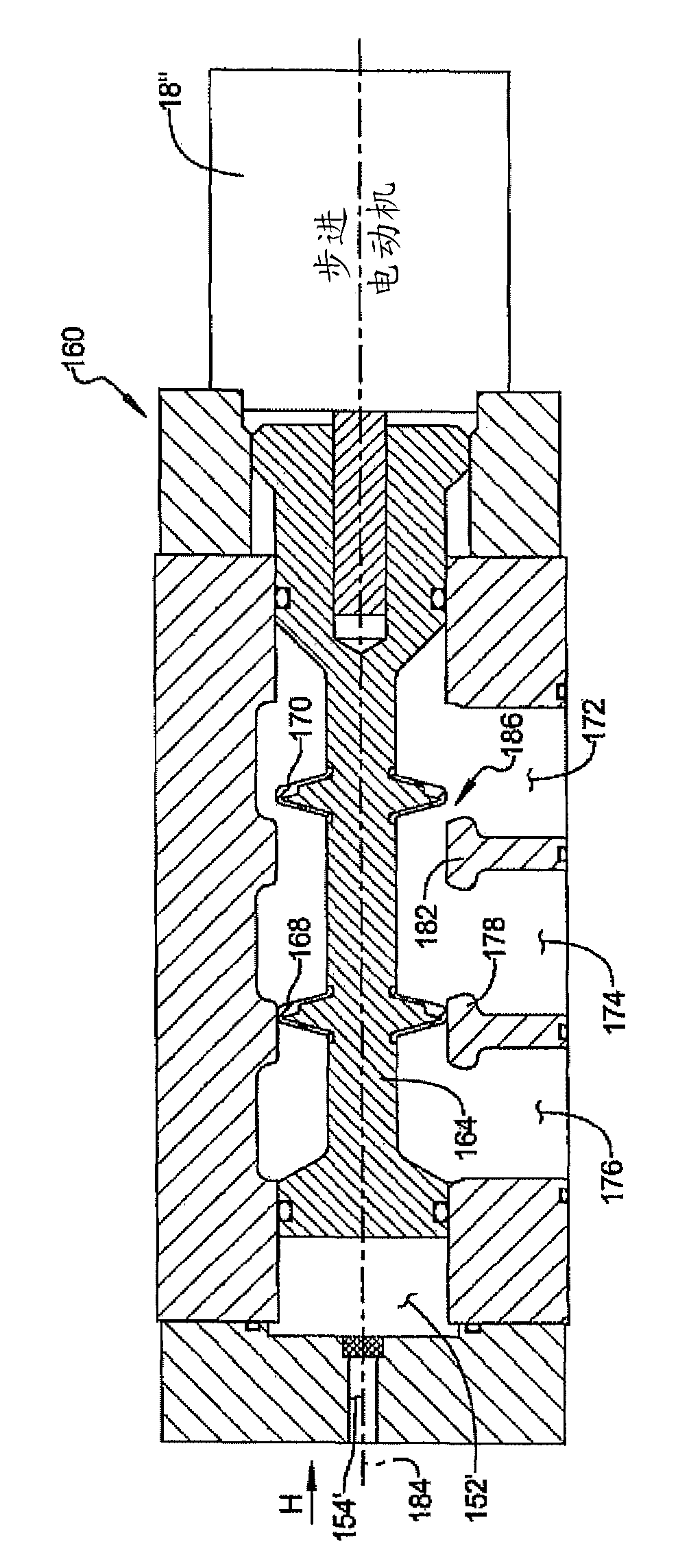
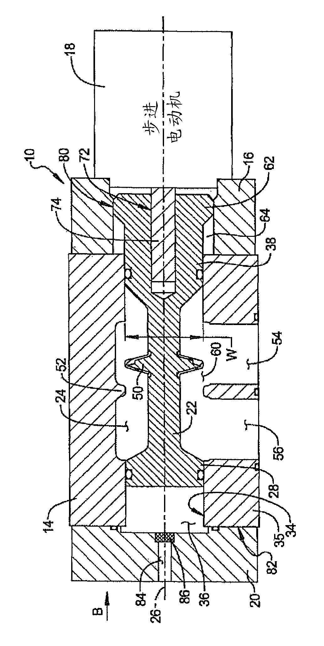
  • Stepper motor operated balanced flow control valve
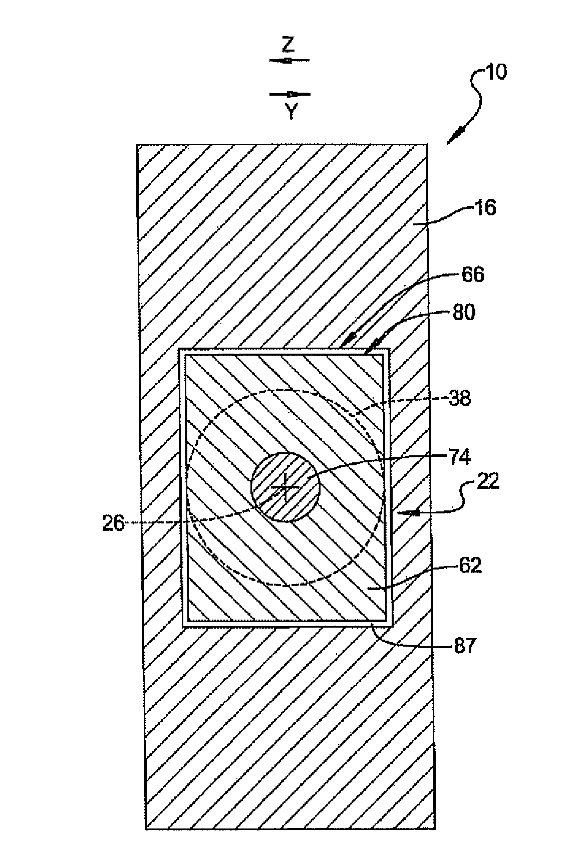
  • Stepper motor operated balanced flow control valve
  • Stepper motor operated balanced flow control valve

Examples


Embodiment Construction

[0025] Example embodiments will now be described more fully with reference to the accompanying drawings.

[0026] These exemplary embodiments are provided so that this disclosure will be thorough, and will fully convey the scope of the invention to those skilled in the art. Numerous specific details are set forth, such as examples of specific components, devices and methods, to provide a thorough understanding of embodiments of the invention. It will be apparent to those skilled in the art that specific details need not be employed, that example embodiments may be embodied in many different forms and that neither should be construed to limit the scope of the invention. In some example embodiments, well-known processes, well-known device structures, and well-known technologies are not described in detail.

[0027] The technical terms used herein are for describing specific exemplary embodiments only, and are not intended to be limiting. As used herein, the singular forms "a",...


PUM


Abstract

A flow control valve includes a body having a body bore oriented coaxially with a longitudinal axis of the body and a seat member extending into the bore. A valve member is slidably disposed in the bore and oriented coaxially with the longitudinal axis of the body. The valve member includes a non-circular geometrically shaped head having a bore. A drive adapter includes a head receiving cavity slidingly receiving the geometrically shaped head of the valve member and preventing axial rotation of the valve member. A stepper motor is connected to the drive adapter, the stepper motor incrementally rotating a shaft engaged with the bore of the valve member. First and second equal diameter pistons of the valve member provide pressure balanced valve member operating positions.

Description

technical field [0001] This invention relates to flow control valves operated by stepper motors. Background technique [0002] This section provides background information related to the present disclosure which is not necessarily prior art. [0003] The flow control valve may be operated by a stepper motor to improve the repeatability of the valve member position of the valve requiring increased precision in controlling flow changes between fully open and / or fully closed positions. Operations that require accurate delivery of fluid volume or pressure to a working device may thus benefit from the precision afforded by stepper motors compared to other known valve actuators. However, known flow control valves operated by stepper motors generally require a gear system or multi-directional component drive system to convert the rotational force of the stepper motor into a longitudinal force used to translate the valve member to either the open valve position or the closed valve ...

Claims


Application Information

Patent Timeline
Patent Type & Authority Patents(China)
IPC IPC(8): F16K31/04F16K21/00F16K37/00
CPCF16K31/04F16K1/02F16K3/00F16K11/065Y10T137/86574Y10T137/86622Y10T137/8671F15B13/0444F16K3/24F16K11/07
Inventor P.A.亚尔K.C.威廉斯
Owner MAC VALVES INC
Learn More