Light and convenient electromagnetic high-energy dynamic compaction device and method and application

A dynamic compaction equipment and electromagnetic technology, applied in the field of portable electromagnetic high-energy dynamic compaction equipment, can solve the problems of heavy construction equipment, limited construction speed, difficult operation, etc. Cost, improved impact speed and impact energy, high intelligence effect

Inactive Publication Date: 2013-08-14
GUANGDONG UNIV OF TECH
View PDF5 Cites 9 Cited by
  • Summary
  • Abstract
  • Description
  • Claims
  • Application Information

AI Technical Summary

Benefits of technology

Inventions described earlier are related to improving the carrying capacity and maneuverability of large industrial machines like hydraulic excavators. These improvements help them work faster without being forced into hard conditions where they may damage their components. Additionally, these inventors provide an improved way to measure impact forces while also reducing costs associated therewith compared to existing methods. Overall, these technical benefits make the machine easier to handle and move around indoors when needed.

Problems solved by technology

This patented technical problem addressed in this patents relates to improving the mechanical properties of foundations through adding or replacing static loadings like dumps without causing damage on surrounding structures such as roads, buildings, bridges, power grids, and support bases.

Method used


Image

  • Light and convenient electromagnetic high-energy dynamic compaction device and method and application
  • Light and convenient electromagnetic high-energy dynamic compaction device and method and application
  • Light and convenient electromagnetic high-energy dynamic compaction device and method and application

Examples


Embodiment

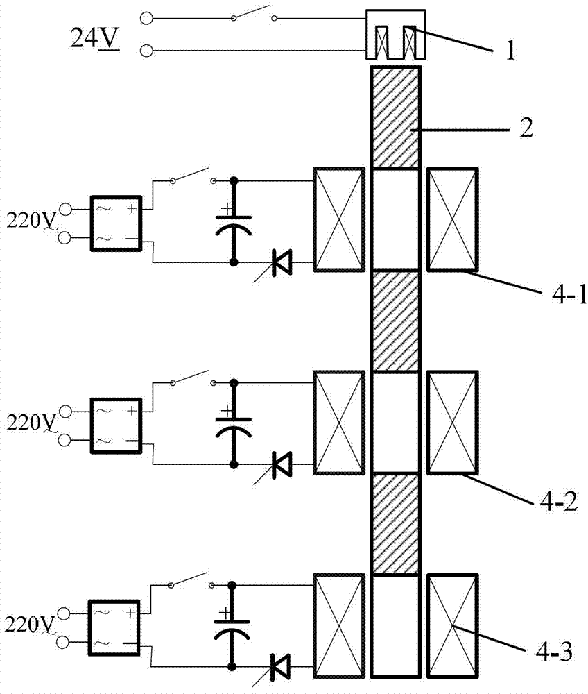
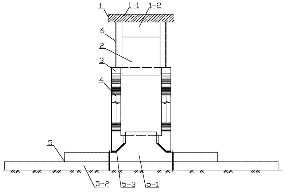
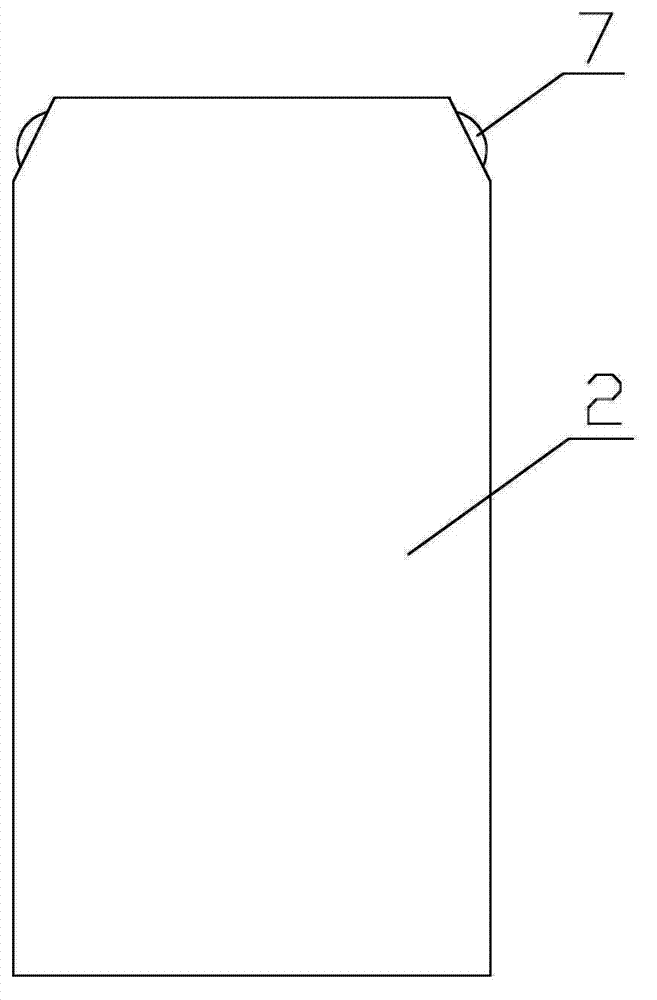
[0041] In this embodiment, a portable electromagnetic high-energy dynamic compaction device, such as figure 1 or figure 2 As shown, it includes an electromagnet assembly 1, an impact rod 2, an outer sleeve 3, an electromagnetic acceleration coil 4 and an impact hammer assembly 5. The electromagnet assembly is arranged above the outer sleeve, the impact rod is arranged in the outer sleeve, and the impact hammer assembly It is located under the outer sleeve. There are multi-stage electromagnetic acceleration coils on the inner wall of the outer sleeve. The electromagnetic acceleration coils at each level are respectively connected to the external circuit control system; the diameter of the impact rod is 300mm-800mm, and there are hook rings on both sides of the top of the impact rod. . Among them, the diameter of the impact rod can be selected according to the different needs of the actual high-energy dynamic compaction, and the hook rings on both sides of the top of the impact ...


PUM

PropertyMeasurementUnit
Diameteraaaaaaaaaa

Abstract

The invention discloses a light and convenient electromagnetic high-energy dynamic compaction device and method and an application. In the light and convenient electromagnetic high-energy dynamic compaction device, an electromagnet assembly is arranged above an outer sleeve, an impact rod is arranged in the outer sleeve, an impact hammer assembly is arranged under the outer sleeve, multiple levels of electromagnetic accelerating coils are arranged on the inner lateral wall of the outer sleeve and respectively connected with circuit control systems externally, and a hook ring is arranged at the top of the impact rod. By means of the method, the impact rod is accelerated through the electromagnetic effect of the multiple levels of electromagnetic accelerating coils during the process that the impact rod falls down to strike the impact hammer, and accordingly the impact energy and speed can be improved. The device is applied to foundation reinforcing in civil engineering, the total weight of the device is less than 1/10 of the weight of a traditional dynamic compaction device with the same compaction energy, the occupied space is greatly reduced, the problem of heavy construction devices, difficult transportation, limited construction speed, high cost, high energy consumption, limited device using space and the like of construction devices in dynamic consolidation method engineering application can be well solved or improved, and the efficient, environment-friendly, safe and wide application can be promoted.

Description


Claims


Application Information

Patent Timeline
Owner GUANGDONG UNIV OF TECH
Why Eureka
Try Eureka