Device and method for forming by stamping at high speed

a technology of stamping and metal parts, applied in the direction of presses, manufacturing tools, presses, etc., can solve the problems of increasing complexity of the techniques put in place to meet these requirements, reducing and requiring high precision during the shaping of parts, so as to achieve more efficient forming and reduce the elastic return of the formed part

Active Publication Date: 2015-12-03
ADM28 S AR L
View PDF4 Cites 2 Cited by
  • Summary
  • Abstract
  • Description
  • Claims
  • Application Information

AI Technical Summary

Benefits of technology

[0023]Specifically, it has been observed surprisingly that when the elastomer is stressed by a hammer (the striking means) moving at high speed, the elastomer has a viscoelastic behavior which results, on the one hand, in more efficient forming (that is to say conforming more to the die) of the part, and, on the other hand, in a reduction of elastic return of the formed part.

Problems solved by technology

In leading industries (aeronautic, space and automotive sectors or other manufacturing industries), the required and necessary precision during the shaping of parts may be high and the techniques put in place to meet these requirements are becoming increasingly complex.
However, one disadvantage of this method lies in the fact that it is only possible to carry out shallow stamping operations in lightweight metals of small thicknesses (for example: aluminum).
In practice, the method is limited to a sheet metal thickness of 1.5 mm.
Another disadvantage of this shaping method is that of the elastic return which occurs after relaxation of the part to be formed.
This effect is greater or lesser depending on the material in question and may prove to be problematic when it is no longer negligible when considering the expected precision.

Method used


Image

  • Device and method for forming by stamping at high speed
  • Device and method for forming by stamping at high speed
  • Device and method for forming by stamping at high speed

Examples


Embodiment Construction

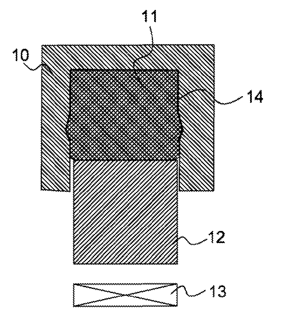
[0043]It will be noted first of all that the figures are not to scale. In the remainder of the description, the term “metal sheet” is used to denote the part to be formed, but the invention is aimed more generally at a thin plate made of plastic, metal or other material. A plate is referred to as thin when one of its dimensions is significantly smaller than the other two, typically by at least one order of magnitude.

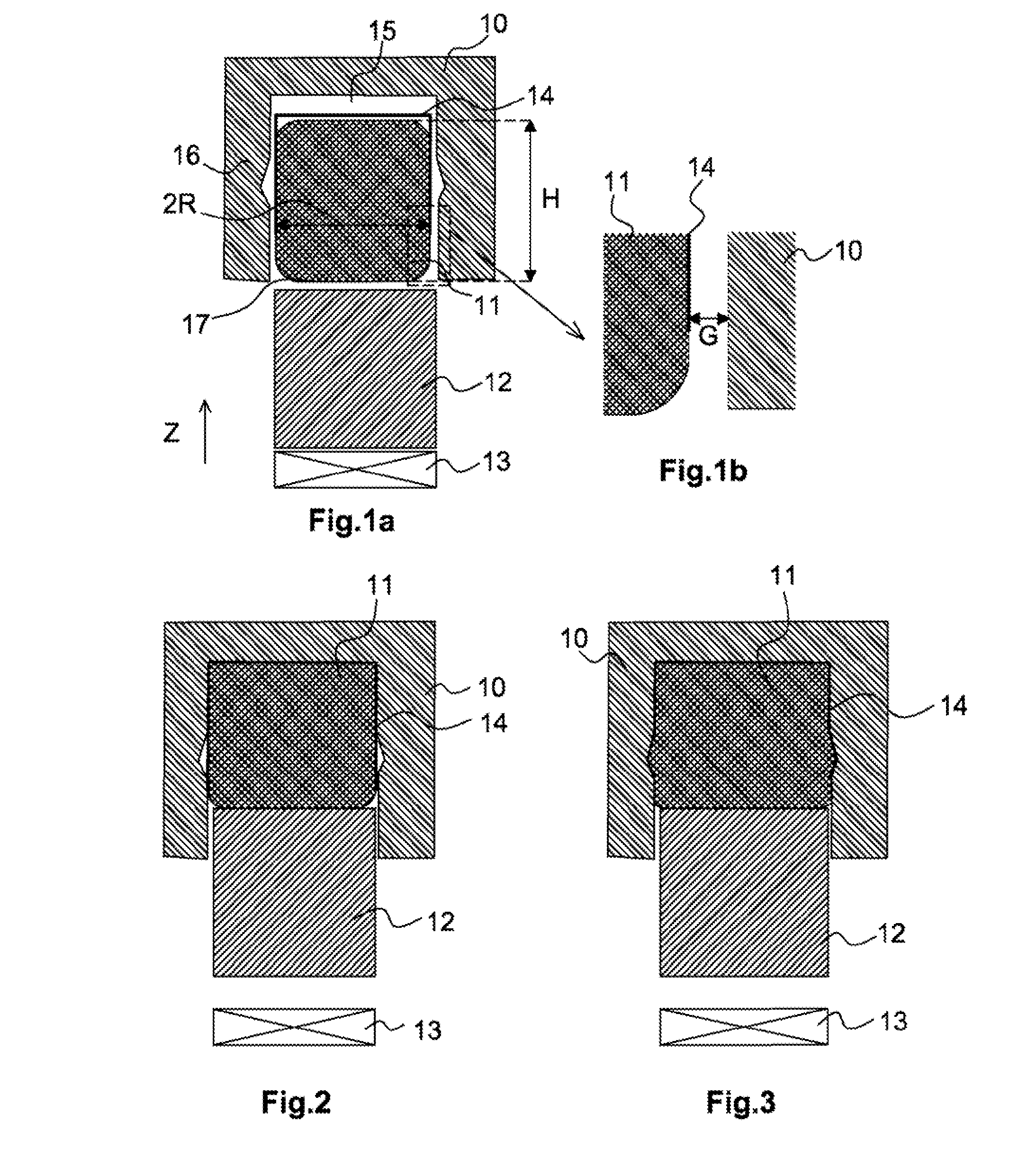
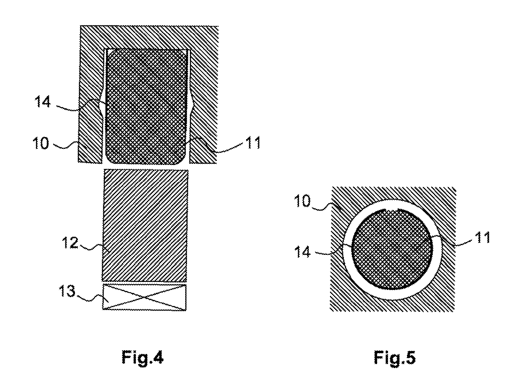
[0044]In one exemplary embodiment of the device, the latter is associated with a die 10. It further comprises an elastomer punch 11, a hammer 12 and a device 13 for generating a magnetic field (of which only the coil is depicted in the figures). This device is adapted to create a high-power magnetic field which can generate a strong acceleration in the hammer 12, with the result that it strikes the punch at high speed. Advantageously, the hammer 12 is independent of the device 13 for generating a magnetic field.

[0045]The die 10, the punch 11 and the hammer 12 are here as...


PUM

PropertyMeasurementUnit
axial speedaaaaaaaaaa
Poisson's ratioaaaaaaaaaa
thicknessaaaaaaaaaa

Abstract

A device and a method for forming by stamping a curved metal sheet. The device includes a punch made of deformable and substantially non-compressible material, a hammer configured to strike the punch along the longitudinal axis Z. A generator to generate a magnetic field configured to impart on the hammer a speed greater than a predetermined speed in the Z direction. The device further includes a matrix of predetermined shape, approximately rotationally symmetrical about the longitudinal axis Z. The punch is rotationally symmetrical about the longitudinal axis and configured to be disposed in front of the matrix. The punch has a longitudinal dimension in the same order of magnitude as its dimension perpendicular to the longitudinal axis Z.

Description

[0001]The present invention relates to the field of forming materials.[0002]It is aimed more particularly at a device and a method for forming metal parts by stamping.PREAMBLE AND PRIOR ART [0003]In leading industries (aeronautic, space and automotive sectors or other manufacturing industries), the required and necessary precision during the shaping of parts may be high and the techniques put in place to meet these requirements are becoming increasingly complex.[0004]When a metal part is to be shaped, stamping is very often the chosen method, since this method is reliable and can be controlled very readily. Stamping consists in a plastic deformation of a plate of material, under the action of a pressure, so as to give the plate the shape of a predetermined mold. Even though the technique is generally used on metal materials (steel, aluminum, etc.), it can also be applied to numerous plastics materials such as PVC, polyethylene, polycarbonate, etc.[0005]One of the variants for carryi...

Claims


Application Information

Patent Timeline
Patent Type & Authority Applications(United States)
IPC IPC(8): B21D22/10B30B1/42
CPCB30B1/42B21D22/10B21D22/105B21J5/04B21C37/294B21D26/14
Inventor PLAU, ERAN
Owner ADM28 S AR L
Why Eureka
Try Eureka