Real vehicle impact test system for double-roller braking railway vehicle

A test system and rail vehicle technology, applied in the field of double-drum brake type rail vehicle real vehicle impact test system, can solve the problems of high energy level during impact, large impact area, and inability to use directly for reference, and achieve simple and easy operation , Construct scientific and reasonable effects

Active Publication Date: 2014-07-30
CENT SOUTH UNIV
View PDF6 Cites 2 Cited by
  • Summary
  • Abstract
  • Description
  • Claims
  • Application Information

AI Technical Summary

Problems solved by technology

[0005] The two technical solutions disclosed above, although they can be applied in the automotive field, they cannot be directly used in the impact test of rail vehicles.
The fundamental reason is the particularity of the structure of rail vehicles, which are large in size, mass, and large in impact area, generally not less than 4 meters by 4 meters; especially rail vehicles running on high-speed rails have high speeds and high energy levels during impact, so they cannot For direct reference, it is necessary to redevelop the real vehicle crash test system for rail vehicles

Method used


Image

  • Real vehicle impact test system for double-roller braking railway vehicle
  • Real vehicle impact test system for double-roller braking railway vehicle
  • Real vehicle impact test system for double-roller braking railway vehicle

Examples


Embodiment 1

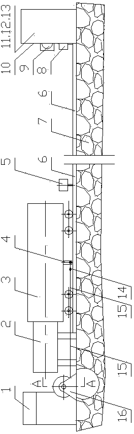
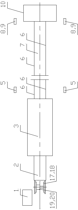
[0054] A steel rail 6 is set on the foundation 7 between the launcher 2 and the impact wall 10; the real vehicle 3 is placed on the steel rail 6, and the launcher 2 is installed on the end of the real vehicle 3 facing away from the impact wall 10; one or both sides of the steel rail 6 Collision velocity measuring device 8 and high-speed photographing device 9 are installed, and the vertical line of impact velocity measuring device 8 and high-speed photographing device 9 is all located in the plane formed by the end face of impact wall 10 facing the real vehicle 3 one end; impact velocity measuring device is installed on both sides of impact wall 10 Device 8 and high-speed photographing device 9, the vertical line of impact speed measuring device 8 and high-speed photographing device 9 are all located in the plane formed by the end face of the end face of the end face of the real vehicle 3 facing the impact wall 10; , the impact speed measuring device 8, the force measurement ac...

Embodiment 2

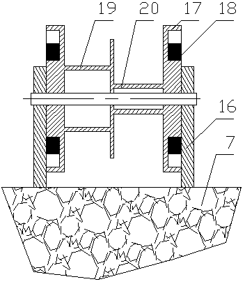
[0061] It is basically the same as Embodiment 1, except that the brake mechanism 18 is a disc brake mechanical brake device.

Embodiment 3、4

[0063] They are basically the same as Embodiments 1 and 2, except that the impact wall 10 is different: the impact wall 10 includes a uniform force plate 11, a force measurement acquisition device and an impact pier 13, the uniform force plate 11 faces the real vehicle 3, and the force measurement acquisition device is located on the uniform force plate 11. Between the force plate 11 and the impact pier 13; the force measurement acquisition device is a force sensor array 12; the central console 1 is electrically connected to the force sensor array 12 and receives impact data.


PUM


Abstract

The invention relates to a real vehicle impact test system for a double-roller braking railway vehicle. The test system comprises a central control desk, an emitter, a real vehicle and an impact wall, wherein the real vehicle is put on a railway between the emitter and the impact wall; an impact speed measuring device and a high-speed photography device are installed on the side face of the impact wall; a brake device, a speed adjusting brake device connector and an adjustment speed measuring device are arranged and used in the working condition adjusting process; the brake device is a brake mechanism with double rollers and comprises a fixed pulley, a steel wire rope, a rack, a brake wheel, a brake mechanism body, the big roller and the small roller, the brake wheel, the big roller and the small roller are of an integrated structure, and the directions of the steel wire rope winding around the big roller and the small roller are opposite. In the impact test process, the brake device breaks away from the speed adjusting brake device connector, and the central control desk controls the relates devices to receive and store data; the unpowered free sliding distance of the real vehicle is at least 1.1 times the effective travel of the emitter, and the test impact speed of the real vehicle and the impact wall is not smaller than 25 km/h.

Description

technical field [0001] The invention relates to a double-drum braking type rail vehicle actual vehicle impact test system. Background technique [0002] Train collision accidents seriously threaten the safety of passengers. In order to reduce the losses caused by train collision accidents, the development of impact-resistant and energy-absorbing car bodies is an important way to reduce the losses caused by train collision accidents, and it is also an inevitable trend in the development of the world's railway passenger car body structures (including urban rail transit vehicles). In the study of the crashworthiness of rail vehicle structures, the real vehicle impact test is an irreplaceable research method that can truly reflect the impact process. The crashworthy and energy-absorbing vehicle body must be developed based on the actual vehicle crash test. [0003] Chinese patent application number is 200610046823.3, and the name is called " automobile passive safety system co...

Claims


Application Information

Patent Timeline
Patent Type & Authority Applications(China)
IPC IPC(8): G01M7/08G01M17/08
Inventor 田红旗梁习锋许平鲁寨军高广军张健谢素超
Owner CENT SOUTH UNIV
Why Eureka
Try Eureka