
Unidirectional limitable hinged support for hinging pipe frame column foot and construction method of unidirectional limitable hinged support

A construction method and hinge support technology are applied in the field of independent movable pipe racks, which can solve the problems affecting the effectiveness of column hinges, poor rotatability of half hinges, and aging and hardening of elastic cushions, so as to avoid instability, connection and stability. Ease of assembly and reduced material consumption

Active Publication Date: 2015-01-14
ARCHITECTURAL DESIGN & RES INST OF SOUTHEAST UNIV CO LTD
View PDF6 Cites 0 Cited by
  • Summary
  • Abstract
  • Description
  • Claims
  • Application Information

AI Technical Summary

Problems solved by technology

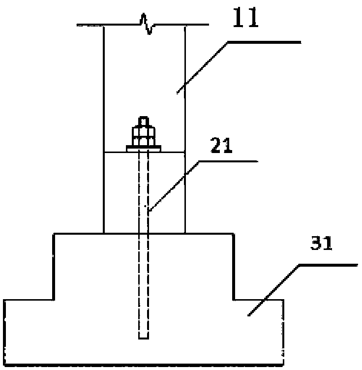
A large number of concrete column feet in the damaged pipe frame are crushed, which shows that the rotatability of this form of half-hinge is poor
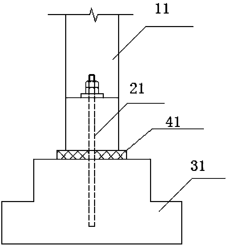
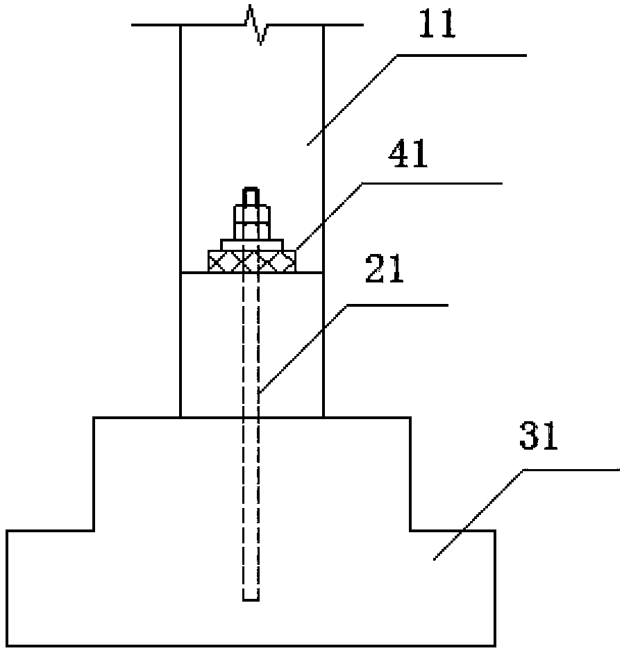
Even if an elastic cushion (linoleum laminate) is added at the column hinge, such as figure 2 , 3 , The structure shown in 4 improves the rotation of the column hinge, but the elastic cushion will gradually age and harden with the wind and sun, and eventually lose its elasticity, thus affecting the effectiveness of the column hinge

Method used


Image

  • Unidirectional limitable hinged support for hinging pipe frame column foot and construction method of unidirectional limitable hinged support
  • Unidirectional limitable hinged support for hinging pipe frame column foot and construction method of unidirectional limitable hinged support
  • Unidirectional limitable hinged support for hinging pipe frame column foot and construction method of unidirectional limitable hinged support

Examples


Embodiment Construction

[0026] The present invention will be further described in detail below in combination with specific embodiments.

[0027] Image 6 It is a structural schematic diagram of the one-way limitable hinge support of the present invention, Figure 7 for Image 6 left view of , refer to Image 6 , 7 As shown, the one-way limitable hinge support used at the foot of the hinged pipe frame includes an upper structure and a lower structure, wherein the upper structure includes a hinge support top plate 2, a hinge support ear plate 3, a hinge support limit Position plate 4, hinge support top plate stiffener 7; hinge support ear plate 3, hinge support limit plate 4 are all welded to the bottom of hinge support top plate 2, and limit plate 4 is located in the middle of the bottom of hinge support top plate 2, Two hinge support ear plates 3 are symmetrically and parallelly arranged on both sides of the limit plate 4 (the ear plate 3 is longer than the limit plate 4), and the top plate stif...


PUM


Abstract

The invention relates to a unidirectional limitable hinged support for a hinging pipe frame column foot and a construction method of the unidirectional limitable hinged support. The unidirectional limitable hinged support is characterized in that the hinged support is formed by linkage of an upper structure and a lower structure, the upper structure comprises a hinged support top plate, a limiting plate is welded in the middle of the bottom of the hinged support top plate, and two side plates are symmetrically and parallelly arranged on two sides of the limiting plate. Top plate stiffening plates are vertically arranged in the middle of the side plates and welded with the side plates and the top plate at the same time. The lower structure comprises a hinged support bottom plate and a hinged support supporting plate, and the hinged support supporting plate is uprightly welded on the hinged support bottom plate and provided with a top portion formed by two symmetrical inclined planes. Temporary fastening holes are reserved on the side plates and the hinged support supporting plate and are overlaid when the hinged support does not rotate leftwards and rightwards, and the side plates and the hinged support supporting plate are fastened by temporarily inserting pins into the temporary fastening holes. By the unidirectional limitable hinged support for hinging the pipe frame column foot, top displacement of a pipe frame is realized, instability caused by overlarge rotating angle of the pipe frame can be avoided, the unidirectional limitable hinged support is simple and direct to assemble, only vertical load is transmitted to a base from the pipe frame via the hinged support, the pipe frame is only stressed by concentric force, and a large number of construction materials are saved.

Description

technical field [0001] The invention relates to an independent movable pipe support which can be widely used in pipeline engineering, especially suitable for independent movable pipe supports with frequent deformation, large deformation value and changeable deformation direction of pipelines, such as heating pipelines and pneumatic conveying pipelines , water supply pipes and other independent movable pipe racks. Pipe frames can be reinforced concrete structures or steel structures. Background technique [0002] Pipe support is an important part of pipeline engineering design. According to the structural system, it can be divided into independent pipe support and stringer type pipe support, among which independent pipe support is the most commonly used form of pipe support. Independent pipe racks are divided into fixed pipe racks and movable pipe racks according to whether the top of the column can be moved, and are divided into reinforced concrete structures and steel str...

Claims


Application Information

Patent Timeline
Patent Type & Authority Patents(China)
IPC IPC(8): E04B1/36E04G21/00
Inventor 侯向煜
Owner ARCHITECTURAL DESIGN & RES INST OF SOUTHEAST UNIV CO LTD
Learn More