Elastic structural elements with through-turn geometry

A technology of elastic structural parts and geometric shapes, which is applied in the direction of spring components, springs, and low internal friction springs composed of several springs, can solve the problems that the transition state is difficult to be uniform and coherent, and the rigid-flexible balance point is difficult to determine, etc., to achieve The effect of widening the range of materials used and the selection of a wide range of material mechanical properties

Active Publication Date: 2015-12-02
SUS LAB FOR IND SCI & TECH
View PDF8 Cites 0 Cited by
  • Summary
  • Abstract
  • Description
  • Claims
  • Application Information

AI Technical Summary

Problems solved by technology

For example, the bow plate bracket and leaf spring of the automobile chassis are typical. The structural parts in this process must be made of elastic materials and the load-bearing process, the transition state of elastic layers and sequential realization is difficult to be uniform and coherent; the rigid-flexible balance point is difficult to determine

Method used


Image

  • Elastic structural elements with through-turn geometry
  • Elastic structural elements with through-turn geometry
  • Elastic structural elements with through-turn geometry

Examples


Embodiment 1

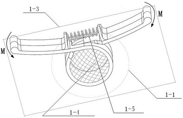
[0026] This embodiment is a kind of elastic structure with a single through-type rotary geometry, see figure 1 .

[0027] Through the pre-deformation storage in the dotted line range indicated in 1-1, the elastic capacity of the integrated material, especially the weak elastic capacity of the integrated rigid material, is used to obtain the elastic bending moment, and through the structure’s own traversal form, the structure moves within a limited space. The direction of elastic deformation of structural parts can be constrained, and the geometric displacement of structural parts can be controlled, so that the elastic bending moment M always acts on the symmetry plane 1-3 of the structure, ensuring that the stress-bearing state and elastic deformation of structural parts are in a stable state, and the load-bearing function be reliably achieved. Devices that redistribute the stress state of the elastic strain process, such as rubber, silicone rubber 1-4, spring 1-5, etc., can ...

Embodiment 2

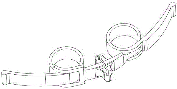
[0029] This embodiment is an elastic structural member with a continuous traversing rotary geometry to adapt or adjust the structural elastic capacity required for load bearing under different dynamic states (the process also includes the realization of both rigidity and flexibility and even rigid load bearing form) . see figure 2 .

Embodiment 3

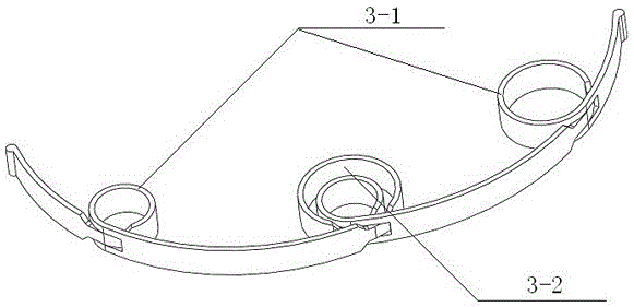
[0031] This embodiment is an elastic structural member with continuous and repeatable (such as 3-1) or helical (such as 3-2) traversing rotary geometry to adapt or adjust the load under different dynamic states. The required structural elasticity (the process also includes the ability to achieve both rigidity and flexibility and even a rigid load-bearing form). see image 3 .


PUM


Abstract

An elastic member can combine flexibility and rigidity, and can implement functions of buffering and shock absorption while effectively supporting a vehicle body. On end of the elastic member is turned and bent towards the other end, and passes through the body of the elastic member. The turned and bent part forms a turned portion (3). Portions of the turned portion (3) extending towards two ends form a first arm (1) and a second arm (2). The turned portion (3) pre-stores deformation of a material to integrate an elastic capability of the material and specifically gather a weak elastic capability of a rigid material, thereby obtaining a higher elastic bending moment, and providing functions of buffering and shock absorption while bearing is provided. For a flexible material, the flexible material can be restrained by using the turned portion to increase rigidity and reduce randomness of deformation of the flexible material, thereby combining flexibility and rigidity. An elastic structural member capable of implementing a bearing capability combining rigidity and flexibility. The structural member has a geometric shape of penetration type turn, and is not limited by a penetrated space size.

Description

technical field [0001] The invention relates to the bearing application field of various engineering and equipment structural parts. Background technique [0002] Structure is a form of material movement, a space force system, and structural parts are part of the force system. This patent expression focuses on structural parts rather than structures. [0003] When the structure and structural parts have sufficient elasticity but insufficient rigidity, it is often difficult to effectively support the load. Therefore, when realizing the structural shape of the engineering effective support load, it is expected that it has both rigidity and flexibility (especially alternating and pulse loads). Stability), so elastic materials are often used to make structural parts to achieve balance: on the one hand, the elastic structural parts are layered and sequential to achieve elasticity; on the other hand, the elastic structural parts are superimposed or combined with auxiliary structur...

Claims


Application Information

Patent Timeline
Patent Type & Authority Patents(China)
IPC IPC(8): F16F1/00F16F3/00
CPCF16F1/02F16F1/027F16F1/10F41B5/12B65G19/22F16F1/18F16F3/02F16F3/12
Inventor 苏章仁肖艳芬
Owner SUS LAB FOR IND SCI & TECH
Why Eureka
Try Eureka