Gas-liquid separator

A technology of gas-liquid separator and air inlet end, which is applied in separation methods, dispersed particle separation, vacuum cleaners, etc., and can solve problems such as complex assembly process, high material cost, and complex structure of filter components

Active Publication Date: 2016-09-21
ZHEJIANG SANHUA INTELLIGENT CONTROLS CO LTD
View PDF4 Cites 0 Cited by
  • Summary
  • Abstract
  • Description
  • Claims
  • Application Information

AI Technical Summary

Problems solved by technology

[0008] As can be seen from the above description, the structure of the filter components in the gas-liquid separator is relatively complex, resulting in complex assembly processes and high material costs

Method used


Image

  • Gas-liquid separator
  • Gas-liquid separator
  • Gas-liquid separator

Examples


Embodiment Construction

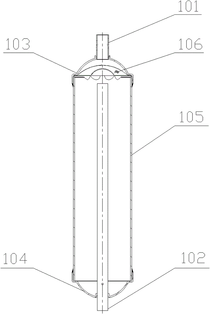
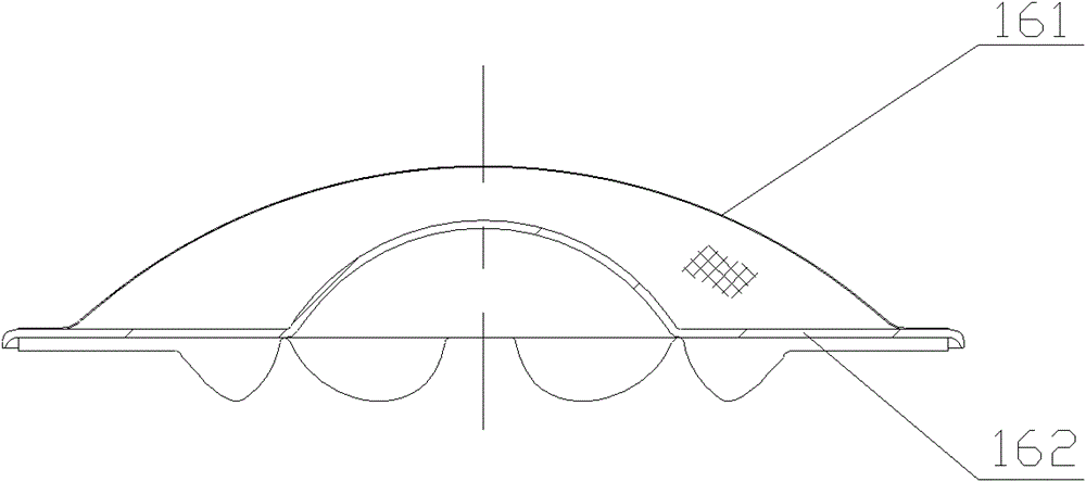
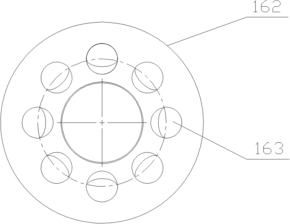
[0034] The core of the invention is to provide a gas-liquid separator used in a refrigeration system. The gas guide element of the gas-liquid separator has simple structure, simple assembly process and low material cost.

[0035] In order to enable those skilled in the art to better understand the solution of the present invention, the present invention will be further described in detail below in conjunction with the accompanying drawings and specific embodiments.

[0036] The orientation words such as upper and lower involved in this article are all defined based on the vertically downward orientation of the outlet pipe of the gas-liquid separator. It should be understood that the use of the orientation words should not limit the scope of protection claimed in this application.

[0037] Please refer to Image 6 , Figure 7 with Figure 8 , Image 6 It is a structural schematic diagram of a specific embodiment of the gas-liquid separator provided by the present invention;...


PUM


Abstract

The invention discloses a gas-liquid separator, which is used in a refrigeration system, comprising a cylinder body, an inlet pipe fixedly connected to the upper end of the cylinder body, an outlet pipe fixedly connected to the lower end of the cylinder body, and an air guide element, The air guiding element further includes a baffle, a flange at one end of the baffle and a bottom plate at the other end of the baffle; the baffle is located above the outlet pipe and blocks the air inlet of the outlet pipe; the The flange is fixedly connected to the inner wall of the cylinder; the bottom plate is fixedly connected to the side wall of the inlet end of the outlet pipe. The air guiding element provided by the invention is processed by steel plate with simple processing technology, which can not only effectively prevent liquid from entering the outlet pipe and avoid liquid shock to the compressor, but also can replace the positioning device to fix the outlet pipe.

Description

technical field [0001] The invention relates to a gas-liquid separator, in particular to a gas-liquid separator applied to a refrigeration system. Background technique [0002] Gas-liquid separators are generally used in refrigeration systems and are installed between the evaporator and the compressor. The main function of the gas-liquid separator is to separate the gaseous and liquid refrigerants, so that the refrigerants enter the compressor from the suction port of the compressor in the form of gas, to prevent liquid shock to the compressor, and return the refrigerated oil to the compressor at the same time. Lubricate the compressor to ensure the normal operation of the compressor and store part of the liquid refrigerant. [0003] Please refer to figure 1 , figure 1 It is a schematic diagram of the structure of a typical gas-liquid separator. [0004] The gas-liquid separator usually includes a cylinder 105 with an inner chamber, an upper end cover 103 is arranged abo...

Claims


Application Information

Patent Timeline
Patent Type & Authority Patents(China)
IPC IPC(8): F25B43/00
CPCF25B43/006F25B2400/23B01D45/12B01D45/16A47L9/1683B04C5/103B01D45/08F25B43/00
Inventor 不公告发明人
Owner ZHEJIANG SANHUA INTELLIGENT CONTROLS CO LTD
Why Eureka
Try Eureka