Control circuit for constant temperature and constant temperature device

A technology of control circuit and constant temperature device, which is applied in the direction of using electric mode for temperature control, etc., can solve the problems of high energy consumption of the control coil, unbalanced effect, easy to be broken down, etc., and achieves low driving power and small electromagnetic interference. , the effect of reducing electromagnetic interference

Inactive Publication Date: 2013-08-14
DONGGUAN KEBAO TESTING EQUIP
View PDF7 Cites 2 Cited by
  • Summary
  • Abstract
  • Description
  • Claims
  • Application Information

AI Technical Summary

Problems solved by technology

[0002] In the prior art, there are some constant temperature and mechanisms in constant temperature devices that will be turned on or off according to the needs of the working environment. Usually, an AC contactor is used for breaking control, which has the following disadvantages: the control coil consumes a lot of energy, It can't achieve the balance effect, it is easy to be broken down, and the noise is loud when working

Method used


Image

  • Control circuit for constant temperature and constant temperature device

Examples


Embodiment Construction

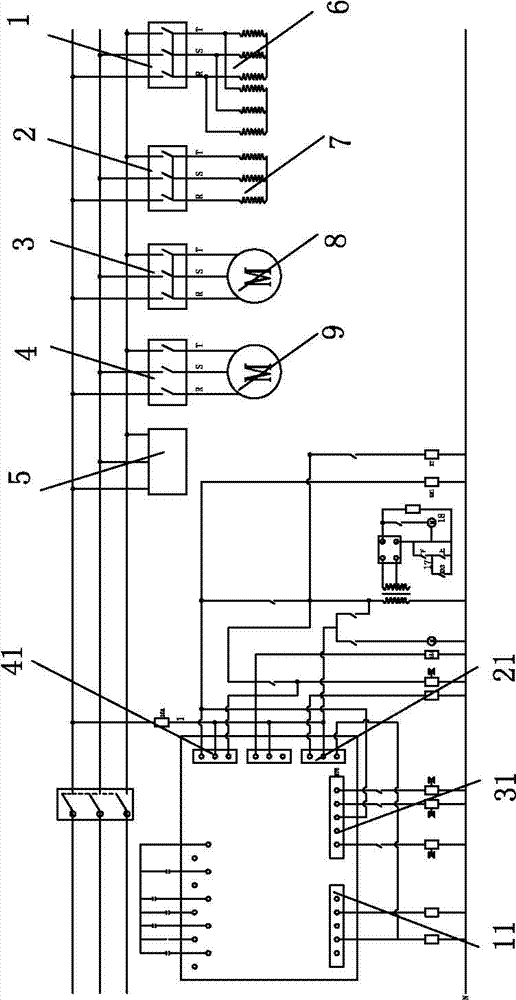
[0008] refer to figure 1 As shown, a control circuit for constant temperature and constant temperature devices is designed, and a control circuit board is provided. The control circuit board is provided with a primary refrigeration motor output control interface 41, a secondary refrigeration motor output control interface 31, and a heating device output control interface 21. . The output control interface 11 of the humidifying device, which also includes a primary cooling motor 9, a secondary cooling motor 8, a heating device 7, and a humidifying device 6 connected to the three-phase power supply through four solid state relays 1, 2, 3, and 4 respectively. The four solid state relays 1, 2, 3, and 4 of the first-stage refrigeration motor 9, the second-stage refrigeration motor 8, the heating device 7, and the humidification device 6 are respectively connected to the corresponding output interfaces 11, 21, 31, and 41 on the control circuit. connect.

[0009] In the above-menti...


PUM


Abstract

The invention discloses a control circuit for constant temperature and a constant temperature device, which comprises a control circuit board, and further comprises a primary refrigeration motor, a secondary refrigeration motor, a heating device, and a humidifying device all connected with a triphase power supply through solid-state relays, wherein a primary refrigeration motor output control interface, a secondary refrigeration motor output control interface, a heating device output control interface, and a humidifying device output control interface are arranged on the control circuit board; and the solid-state relays of the primary refrigeration motor, the secondary refrigeration motor, the heating device, and the humidifying device are connected with corresponding output interfaces on the control circuit respectively. According to the control circuit, as the solid-state relays have no machine parts, the contact function is finished by a solid device; as the solid-state relays have no moving parts, the solid-state relays can work in the environment with high impact and vibration; and as intrinsic properties of components of the solid-state relays, high service life and reliability of the solid-state relays are determined.

Description

technical field [0001] The invention relates to a control circuit, in particular to a constant temperature, a control circuit of a constant temperature device. Background technique [0002] In the prior art, there are some constant temperature and mechanisms in constant temperature devices that will be turned on or off according to the needs of the working environment. Usually, an AC contactor is used for breaking control, which has the following disadvantages: the control coil consumes a lot of energy, The balance effect cannot be achieved, it is easy to be broken down, and the noise is loud when working. Contents of the invention [0003] The object of the present invention is to provide a control circuit for a constant temperature and constant temperature device, which can work in a high impact and vibration environment. [0004] A control circuit for constant temperature and constant temperature devices is provided, including a control circuit board, and the control c...

Claims


Application Information

Patent Timeline
Patent Type & Authority Applications(China)
IPC IPC(8): G05D23/19
Inventor 邓廷文
Owner DONGGUAN KEBAO TESTING EQUIP
Why Eureka
Try Eureka