Vehicle-mounted sine wave inverter and inversion control circuit thereof

An inverter control circuit, a vehicle-mounted inverter technology, which is applied to electrical components, output power conversion devices, and AC power input to DC power output, etc. It can solve problems such as complex calculation processing, achieve fast response, and save resources. , output stable effect

Active Publication Date: 2013-08-14
DOMETIC SHENZHEN ELECTRONICS CO LTD
View PDF5 Cites 5 Cited by
  • Summary
  • Abstract
  • Description
  • Claims
  • Application Information

AI Technical Summary

Problems solved by technology

[0005] The technical problem to be solved by the present invention is to provide an inverter control circuit of a sine wave vehicle-mounted inverter and corresponding vehicle-mounted inverter

Method used


Image

  • Vehicle-mounted sine wave inverter and inversion control circuit thereof
  • Vehicle-mounted sine wave inverter and inversion control circuit thereof
  • Vehicle-mounted sine wave inverter and inversion control circuit thereof

Examples


Embodiment Construction

[0022] In order to make the object, technical solution and advantages of the present invention clearer, the present invention will be further described in detail below in conjunction with the accompanying drawings and embodiments.

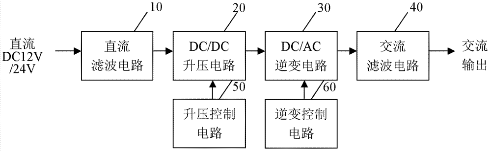
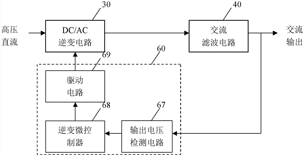
[0023] see Figure 4 , is a module block diagram of the voltage stabilizing inverter control circuit of the sine wave vehicle-mounted inverter according to the present invention. Such as Figure 4 As shown, the inverter control circuit 60 of the sine wave vehicle inverter at least includes a voltage detection circuit 61 , a current detection circuit 62 , a voltage correction module 63 , a SPWM wave generation module 64 and a drive circuit 69 . The circuit of the sine wave vehicle inverter is as follows: figure 1 As shown in , it includes a DC filter circuit 10, a DC / DC boost circuit 20, a DC / AC inverter circuit 30 and an AC filter circuit 40, and a boost control circuit for generating PWM waves to control the DC / DC boost circuit 20 50 and an inv...


PUM


Abstract

The invention relates to a vehicle-mounted sine wave inverter and an inversion control circuit thereof. The inversion control circuit comprises a voltage detection circuit, a current detection circuit, a voltage correction module, an SPWM (Sinusoidal Pulse Width Modulation) wave generation module and a driving circuit, wherein the voltage detection circuit and the current detection circuit are connected with a direct current input end of a DC/AC (Direct Current/Alternating Current) inversion circuit of the vehicle-mounted sine wave inverter and transmit detected direct current input voltage and direct current input current to the voltage correction module, respectively; the voltage correction module corrects the direct current input voltage according to the detected direct current input current and transmits a corrected value of the direct current input voltage to the SPWM wave generation module; and the SPWM wave generation module calculates and outputs an SPWM wave to the driving circuit to drive the DC/AC inversion circuit to convert direct current into stable alternating current. The inverter and the circuit employ direct voltage feedforward control and direct current compensation regulation to allow the output alternating voltage to be stable, complicated detection and calculation of the alternating voltage and proportional integral operation are not required, resources can be saved, and the inverter and the circuit output stably and operate reliably.

Description

technical field [0001] The present invention relates to the technical field of vehicle-mounted inverters, and more specifically, relates to an inverter control circuit of a sine wave vehicle-mounted inverter and a corresponding sine wave vehicle-mounted inverter. Background technique [0002] The module block diagram of the existing vehicle inverter is as follows: figure 1 As shown, it includes a DC filter circuit 10, a DC / DC boost circuit 20, a DC / AC inverter circuit 30 and an AC filter circuit 40, and a boost control circuit 50 for generating PWM waves to control the DC / DC boost circuit 20 And an inverter control circuit 60 for generating SPWM waves to control the DC / AC inverter circuit 30 . After the DC input, first pass through the DC filter circuit 10 to reduce ripple current and suppress electromagnetic interference, then pass through the DC / DC booster circuit 20 to convert DC12V or DC24V to high-voltage direct current, and then pass through the DC / AC inverter circuit...

Claims


Application Information

Patent Timeline
Patent Type & Authority Applications(China)
IPC IPC(8): H02M7/537
Inventor 谢勇万小平
Owner DOMETIC SHENZHEN ELECTRONICS CO LTD
Why Eureka
Try Eureka