Rotating multifunctional platform

A multi-functional, rotating technology, which can be used in the direction of tables whose desktop can rotate on the vertical axis, the combination of two or more pieces of different types of furniture, and tables with variable table heights, which can solve the problem of limiting activity space, taking Picking up items requires people to turn around or turn sideways, which is inconvenient, so as to increase the placement space, facilitate placing or picking up items, and avoid bending under force

Inactive Publication Date: 2013-08-21
NINGBO UNIV
View PDF6 Cites 17 Cited by
  • Summary
  • Abstract
  • Description
  • Claims
  • Application Information

AI Technical Summary

Problems solved by technology

However, because the bedside table is placed on the side of the bed, it is inconvenient for people to turn around or turn sideways to get the items; while the folding table is placed di

Method used


Image

  • Rotating multifunctional platform
  • Rotating multifunctional platform
  • Rotating multifunctional platform

Examples


Embodiment 1

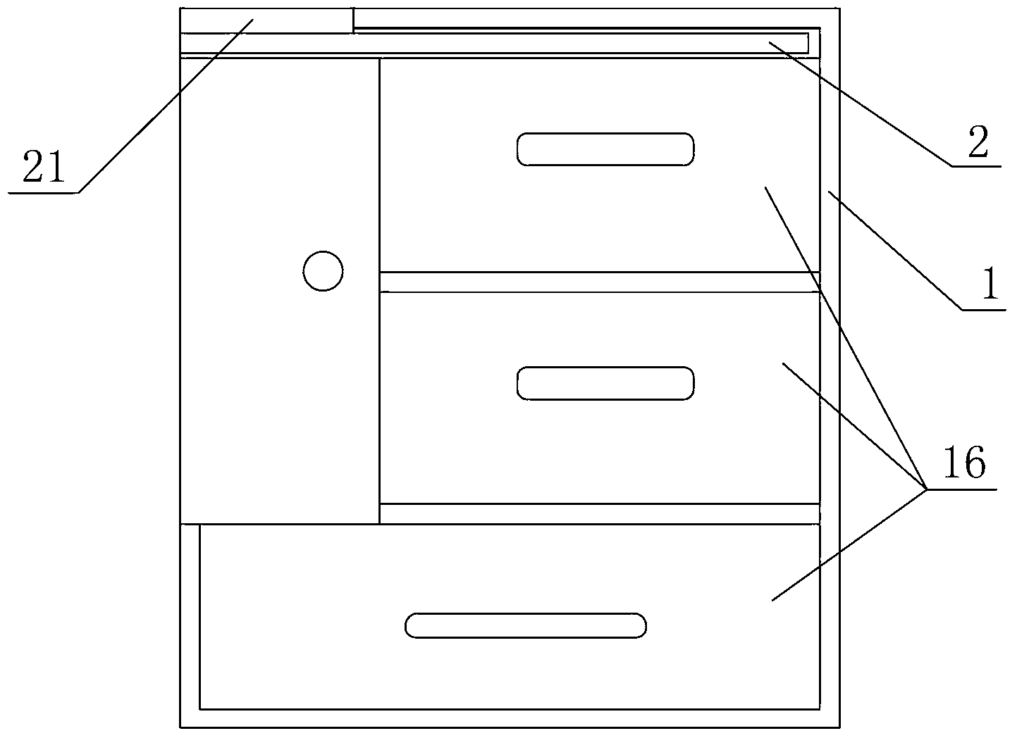
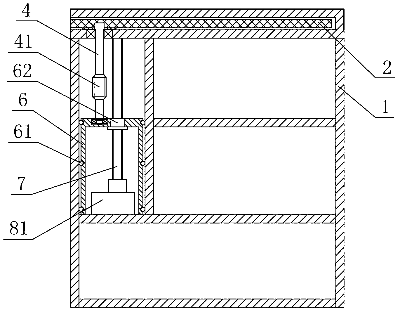
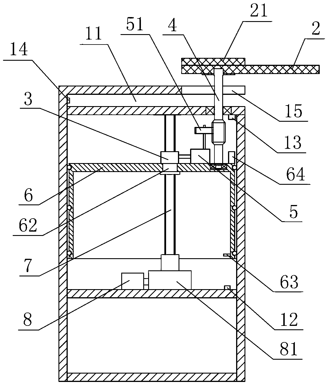
[0020] Embodiment 1: As shown in the figure, a rotary multifunctional platform includes a main body 1 and a rotating plate 2. The upper end of the main body 1 is provided with a cavity 11 with openings on both sides, and the rotating plate 2 is located in the cavity 11. The main body 1 is provided with a control system (not shown in the figure) and a rotating drive device for the rotating plate 2, and a lifting drive device. The rotating plate driving device includes a first motor 3, a rotating shaft 4 and a first reduction box assembly 5. The lifting drive device includes a lifting Platform 6, screw mandrel 7 and second motor 8, lifting platform 6 is arranged in the main body 1, the left and right sides of lifting platform 6 are connected with a plurality of rollers 61 respectively, the first motor 3 and the first reduction box assembly 5 are fixedly installed On the lifting platform 6, the rotating shaft 4 is connected to the lifting platform 6, the rotating plate 2 is fixedl...

Embodiment 2

[0021] Embodiment 2: As shown in the figure, other structures are the same as Embodiment 1. The difference is that the lifting drive device of the rotating plate 2 includes a lifting platform 6 and a second motor 8. The lifting platform 6 is arranged in the main body 1, and the first motor 3 and the first reduction box assembly 5 are fixedly installed on the lifting platform 6, the rotating shaft 4 is axially connected to the lifting platform 6, the second motor 8 is fixedly installed in the main body 1, and the drive shaft of the second motor 8 is coaxially fixed with a drive Bevel gear 82, the main body 1 is provided with a coaxial driven bevel gear 83 and a driving spur gear 84, the driving bevel gear 82 is meshed with the driven bevel gear 83, the main body 1 is connected with a driven spur gear 85, and the driving The spur gear 84 is meshed with the driven spur gear 85, and the lifting platform 6 is integrally provided with a rack 63, the driven spur gear 85 is meshed with...

Embodiment 3

[0022] Embodiment 3: As shown in the figure, other structures are the same as Embodiment 1. The difference is that an auxiliary rotating plate 9 and an auxiliary rotating shaft 91 are also provided. The auxiliary rotating plate 9 is located in the cavity 11 and below the rotating plate 2. An auxiliary lifting platform 92 is fixedly arranged on the table 6, the auxiliary rotating shaft 91 is axially connected to the auxiliary lifting platform 92 and coaxially sleeved on the rotating shaft 4, and a third motor 93 and a third reduction box assembly 94 are fixedly arranged on the auxiliary lifting platform 92 , the drive shaft of the third motor 93 is fixedly connected to the input shaft of the third reduction box assembly 94, the output shaft of the third reduction box assembly 94 is coaxially fixed with an auxiliary worm gear 95, and the auxiliary shaft 91 is coaxially fixed with an auxiliary The worm 96, the auxiliary worm gear 95 and the auxiliary worm 96 are meshed, and the th...


PUM


Abstract

The invention discloses a rotating multifunctional platform. The platform is characterized by comprising a main body and a rotating plate. A hollow cavity with openings formed in two sides is arranged at the upper end portion of the main body, the rotating plate is located in the hollow cavity, and a control system and a rotating driving device of the rotating plate are arranged in the main body. The rotating multifunctional platform has the advantages that the platform is arranged beside a bed, people who sit on or lie in the bed can rotate the rotating plate to the position in front of a user, articles can be conveniently placed and taken, and a movable space of people in the bed is not limited. Furthermore, due to the fact that a lifting driving device of the rotating plate is arranged in the main body, the height of the rotating plate can be adjusted according to the requirement of the user so that the rotating plate can be located at an appropriate height, and the user can conveniently and comfortably use the rotating plate. In addition, due to the fact that an auxiliary rotating plate is further arranged below the rotating plate, when the platform is used, the rotating plate and the auxiliary rotating plate can be rotated out at the same time, and the rotating plate and the auxiliary rotating plate are located at the opposite positions, therefore, stressed deformation after long-time use of the rotating shaft is avoided, and meanwhile a placing space of the user is also increased.

Description

technical field [0001] The invention relates to a storage platform, in particular to a rotary multifunctional platform. Background technique [0002] When people are lying in bed watching TV or surfing the Internet, food or other items are usually placed on the bedside table, or a folding table is placed on the bed and items are placed on the folding table. However, because the bedside table is placed on the side of the bed, it is inconvenient for people to turn around or turn sideways to get the items; while the folding table is placed directly on the bed, although it is more convenient to take items, the legs of the folding table limit people's ability to move around. The activity space on the bed is also inconvenient. Contents of the invention [0003] The technical problem to be solved by the present invention is to provide a rotating multifunctional platform that is convenient for taking food or other items and does not limit the activity space of people on the bed....

Claims


Application Information

Patent Timeline
IPC IPC(8): A47B83/04A47B11/00A47B9/00A47B79/00
Inventor 李国富劳科奇沈彬潘驰吴灵锋温从剑刘莹璇宣国超
Owner NINGBO UNIV
Why Eureka
Try Eureka