
Pipe bending device

A pipe bender and pipe bending technology, which is applied in the field of pipe benders, can solve problems such as easy bending and cracking, and wrinkles in bending parts, and achieve the effects of enhanced performance, reasonable structure, and simple operation

Inactive Publication Date: 2013-08-21
SAIC-GM-WULING AUTOMOBILE CO LTD
View PDF8 Cites 5 Cited by
  • Summary
  • Abstract
  • Description
  • Claims
  • Application Information

AI Technical Summary

Problems solved by technology

For thin-walled stainless steel pipes, this bending forming method is likely to cause serious wrinkles and cracks in the bending parts.

Method used


Image

  • Pipe bending device
  • Pipe bending device
  • Pipe bending device

Examples


Embodiment Construction

[0026] The present invention will be described in further detail below in conjunction with the accompanying drawings.

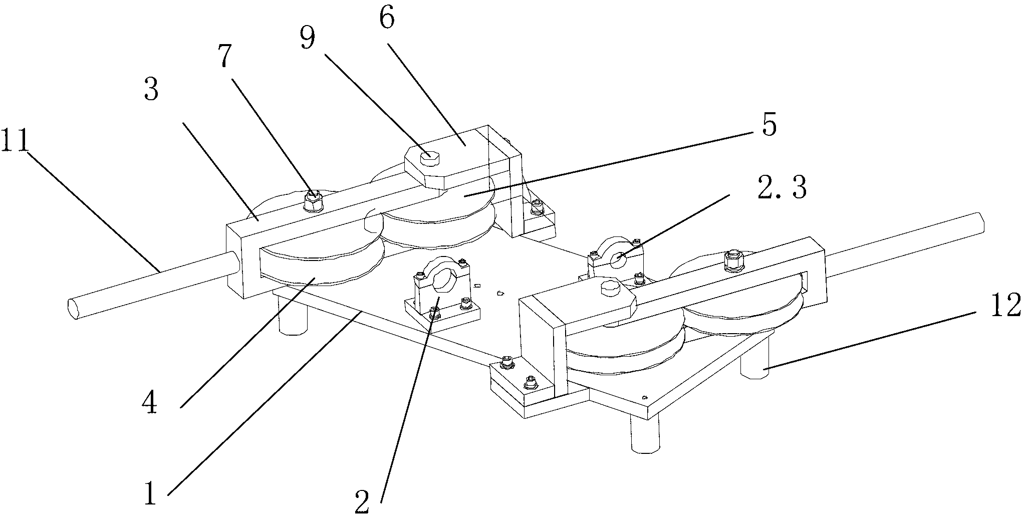
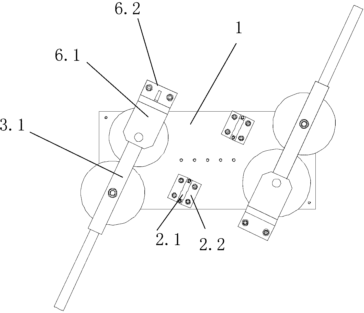
[0027] like Figure 1-6 The shown pipe bender of the present invention includes a workbench 1, a fixing base 2 fixed on the workbench and a pipe bend assembly; the pipe bend assembly includes a horizontal U-shaped connector 3, a The first roller 4 and the second roller 5 arranged horizontally in the inner cavity; the U-shaped connector is composed of an upper plate 3.1, a bottom plate 3.2 and a lower plate 3.3 connected in sequence; between the first roller and the second roller there is a The gap through which the bent stainless steel pipe passes; one end of the first roller is close to the bottom plate of the U-shaped connector; one end of the handle 11 is inserted into the U-shaped connector through the through hole of the bottom plate and pressed against the outer surface of the first roller; the reinforcement plate 6 is a zigzag plate, which is set at t...


PUM

PropertyMeasurementUnit
lengthaaaaaaaaaa
diameteraaaaaaaaaa

Abstract

The invention provides a pipe bending device. The pipe bending device comprises a working table and a fixing base and a pipe bending assembly, wherein the fixing base and the pipe bending assembly are fixedly arranged on the working table. The pipe bending assembly comprises a U-type connecting member arranged transversely, a first idler wheel and a second idler wheel, wherein the first idler wheel and the second idler wheel are horizontally arranged in an inner cavity of the U-type connecting member, and a gap allowing a steel pipe to be bent to penetrate is formed between the first idler wheel and the second idler wheel. One end of a handle penetrates through a base plate of the U-type connecting member and is inserted into and abuts against the outer surface of the first idler wheel, a zigzag type reinforcing plate is arranged at the tail end of the U-type connecting member, a first pin shaft penetrates through the U-type connecting member and the first idler wheel from top to bottom in sequence and then is fixed by a first nut, and a second pin shaft penetrates through the reinforcing plate, the U-type connecting member, the second idler wheel and the working table from top to bottom in sequence and then is fixed by a second nut. The pipe bending device is reasonable in structure, firm, practical, simple in operation and capable of conducting on-site actual matching of bending shapes of different angles on thin-wall stainless steel pipes, the material characteristics of the thin-wall stainless steel pipes are not damaged, and using performance of the thin-wall stainless steel pipes is enhanced.

Description

technical field [0001] The invention relates to a device for bending and forming metal pipes, in particular to a pipe bender. Background technique [0002] In the automotive industry, it is often necessary to bend metal pipes into workpieces with certain curvature, angle and shape. At present, the traditional process of pipe bending is sand filling, scribing, heating, and bending. After heating, the plasticity of the material increases, and the force required for bending is small. The outer layer of the pipe is stretched and becomes longer, and the inner layer is compressed and shortened. However, after heating, the material is easy to oxidize, decarburize, overheat, burn, melt, and the working conditions are poor. For thin-walled stainless steel pipes, this bending forming method is likely to cause serious wrinkles and cracks in the bending parts. Contents of the invention [0003] The present invention is completed in order to solve the deficiencies in the prior art. ...

Claims


Application Information

Patent Timeline
Patent Type & Authority Applications(China)
IPC IPC(8): B21D7/08
Inventor 范健文岑延清罗润生刘琰管菁陈春林
Owner SAIC-GM-WULING AUTOMOBILE CO LTD
Learn More