Hydraulic upsetter loose tooling locking device

A technology of locking device and upsetting machine, which is applied in the driving device of forging press, upsetting press, forging/pressing/hammer device, etc., which can solve problems affecting processing efficiency and achieve the goal of improving processing efficiency and product quality Effect

Inactive Publication Date: 2013-08-21
杜洋
View PDF6 Cites 2 Cited by
  • Summary
  • Abstract
  • Description
  • Claims
  • Application Information

AI Technical Summary

Problems solved by technology

[0002] At present, the method of forming the upsetting tire mold has been widely used, but the existing upsetting tire mold forming process is completed by manual locking operation, so the processing efficiency is affected

Method used


Image

  • Hydraulic upsetter loose tooling locking device

Examples


Embodiment Construction

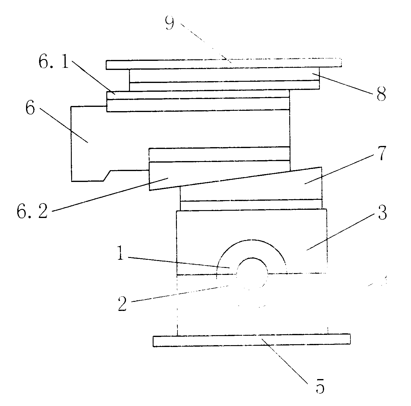
[0009] As shown in the figure, the lower tire plate 4 and the upper tire plate 3 are installed on the machine base 5, the lower mold 2 is embedded in the lower tire plate, and the upper mold 1 is embedded in the upper tire plate; Fixed wedge 7 is arranged; Movable wedge 6.2 and movable block 6 are housed on the fixed wedge; Movable slide plate 6.1, fixed slide plate 8 and top cover 9 are equipped with on the movable block top.

[0010] Working process of the present invention:

[0011] After the upper and lower tire plates and the upper and lower molds formed between the machine base and the top cover are fastened, the movable wedge is driven to run in the direction of the fixed wedge by pushing the movable slide plate and the movable block, and the movable wedge is opposite to the fixed wedge. Generate pressure, press the upper tire plate, and lock the upper mold and the lower mold.


PUM


Abstract

The invention provides a hydraulic upsetter loose tooling locking device. A lower bed mould and an upper bed mould. A lower die is embedded in the lower bed mould. An upper die is embedded in the upper bed mould. A fixed wedge is mounted on the upper bed mould. A movable wedge and a movable block are mounted on the fixed wedge. A movable slide plate, a fixed slide plate and a top cover are mounted on the upper portion of the movable block. During use, the dies can be locked fast, machining efficiency and product quality can be increased, and automatic upsetting of an upsetter can be achieved. The hydraulic upsetter loose tooling locking device is applicable to loose tooling locking during upsetting.

Description

technical field [0001] The invention provides a tooling for an upset forging machine, in particular a tire mold locking device for a hydraulic upset forging machine. Background technique [0002] At present, the method of forming the upsetting tire mold has been widely used. However, the existing upsetting tire mold forming process is completed by manual locking operation, so the processing efficiency is affected. Contents of the invention [0003] In order to realize the locking of the tire mold for upsetting, the invention provides a tire mold locking device for a hydraulic upset forging machine. The device solves the technical problem of membrane locking by installing movable blocks and wedge plates on the tire plate. [0004] The scheme that the present invention solves technical problem adopts is: [0005] A lower tire plate and an upper tire plate are installed on the machine base, a lower mold is embedded in the lower tire plate, and an upper mold is embedded in t...

Claims


Application Information

Patent Timeline
Patent Type & Authority Applications(China)
IPC IPC(8): B21J9/06B21J9/12B21J13/02
Inventor 杜洋
Owner 杜洋
Why Eureka
Try Eureka