An auxiliary high-pressure water jet slit blowout prevention device

A high-pressure water jet and blowout prevention device technology, which is applied in safety devices, boreholes/well components, mining equipment, etc., can solve problems such as blowout holes, achieve the effects of preventing blowout holes, eliminating potential safety hazards, and avoiding life threats

Inactive Publication Date: 2015-09-02
WUHAN UNIV
View PDF6 Cites 0 Cited by
  • Summary
  • Abstract
  • Description
  • Claims
  • Application Information

AI Technical Summary

Problems solved by technology

[0004] The invention aims to solve the problem of nozzle holes that may be generated when high-pressure water jets cut seams in coal seams, thereby providing an auxiliary high-pressure water jet cutting blowout prevention device

Method used


Image

  • An auxiliary high-pressure water jet slit blowout prevention device
  • An auxiliary high-pressure water jet slit blowout prevention device
  • An auxiliary high-pressure water jet slit blowout prevention device

Examples


Embodiment 1

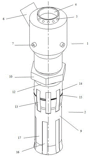
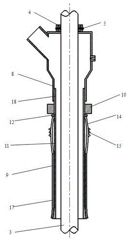
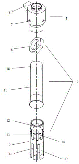
[0017] Below in conjunction with accompanying drawing, the present invention is further described: as Figure 1-3 As shown, an auxiliary high-pressure water jet slit blowout prevention device includes a gathering assembly 1 and a locking assembly 2, and the gathering assembly 1 and the locking assembly 2 are connected by threads; the locking assembly 2 includes an outer casing Sleeve 9, nut 10 and inner sleeve 11, the outer surface of the inner sleeve 11 is in smooth contact with the inner surface of the outer sleeve 9, the nut 10 is arranged on the inner sleeve 11, located between the outer sleeve 9 and the gathering Between component 1.

[0018] The top outlet of the collecting assembly 1 is provided with a sealing ring 4 with a screw 5, and the inner diameter of the sealing ring 4 is slightly larger than the outer diameter of the drill pipe used for drilling; The axis of 6 forms an acute angle with the axis of the main body of the collecting assembly 1; three atomizing noz...

Embodiment 2

[0024] There are 6 rectangular grooves 13, which are used to make the drum-shaped cylinder wall 14 bend upward when the nut is tightened.

[0025] There are 8 rectangular openings 16, which are used to make the bracket 17 open and be stuck in the drilled hole when the nut is tightened.

[0026] All the other technical features are the same as those in Embodiment 1.

Embodiment 3

[0028] There are 10 rectangular grooves 13, which are used to make the drum wall 14 bend upward when the nut is tightened.

[0029] There are four rectangular openings 16, which are used to make the bracket 17 open and be stuck in the drilled hole when the nut is tightened.

[0030] All the other technical features are the same as those in Embodiment 1.

[0031] The present invention is achieved like this:

[0032] 1. Insert the inner sleeve 11 from the bottom of the outer sleeve 9. Due to the horn-shaped opening at the lower part of the inner sleeve 11, the inner sleeve 11 can no longer move up relative to the outer sleeve 9 without applying a large force. ;

[0033] 2. Install the nut 10 on the male thread 18 on the upper end of the inner sleeve 11;

[0034] 3. Insert the assembled part into the drill hole and put it on the drill pipe 3, rotate the nut 10 and press the outer sleeve 9, because the inner sleeve 11 moves up relative to the outer sleeve 9, the drum shape of t...


PUM


Abstract

The invention relates to an anti-spray device for assisting high-pressure water jet slotting. The anti-spray device comprises a packing assembly (1) and a locking assembly (2), wherein the packing assembly (1) is connected with the locking assembly (2) by threads; the locking assembly (2) comprises an outer sleeve (9), a nut (10) and an inner sleeve (11); the outer surface of the inner sleeve (11) is smoothly contacted with the inner surface of the outer sleeve (9); the nut (10) is arranged on the inner sleeve (11), and located between the outer sleeve (9) and the packing assembly (1); the upper part of the outer sleeve (9) is drum-shaped; a plurality of annular convex teeth (15) are axially arranged outside a drum-shaped sleeve wall (14); a plurality of rectangular grooves (13) are uniformly distributed in a radial direction of the drum-shaped sleeve wall (14); an opening at the lower part of the outer sleeve (9) is horn-shaped; and a plurality of rectangular openings (16) are uniformly distributed in a radial direction of a horn-shaped sleeve wall to form a bracket (17). The anti-spray device has the advantages that an incidence rate of orifice spraying can be reduced effectively, so that a great threat of transfinite gas to life safety of coal miners is avoided; a great potential safety hazard in coal mining is eliminated; and the anti-spray device is simple to operate, safe and reliable, and is of great significance in assisting the widely-used high-pressure water jet slotting to prevent the orifice spraying.

Description

technical field [0001] The invention relates to the technical field of coal mining, in particular to an auxiliary high-pressure water jet slit blowout prevention device. Background technique [0002] With the increase of energy demand and the continuous increase of mining intensity, shallow resources are decreasing day by day, and the depth of coal mining in my country is increasing. At present, most coal mines have entered into deep mining. As the mining depth increases, the gas pressure and gas content are getting higher and higher. At the same time, the air permeability is worse, so mining is more difficult and dangerous. In order to prevent gas accidents and ensure mining safety, my country implements the method of "pumping first and then mining" in coal mining, that is, before mining the protective seam coal seam, it is necessary to relieve the pressure of the outburst coal seam at the shallow drilling site or medium-deep drilling site at the top of the coal seam roadwa...

Claims


Application Information

Patent Timeline
Patent Type & Authority Patents(China)
IPC IPC(8): E21F7/00E21B33/06
Inventor 王晓川康勇李登胡毅粟登峰王泽峰
Owner WUHAN UNIV
Why Eureka
Try Eureka