Horizontal flash tank for centrifugal unit

A flash tank and centrifugal technology, which is applied in the internal structure of central air-conditioning centrifugal units, can solve problems such as flash tank liquid level fluctuations and compressor damage, and achieve the effects of increasing energy efficiency ratio, improving cooling capacity, and low noise

Active Publication Date: 2013-08-21
SHANDONG GRAD GROUP
View PDF5 Cites 4 Cited by
  • Summary
  • Abstract
  • Description
  • Claims
  • Application Information

AI Technical Summary

Problems solved by technology

[0004] In the prior art, the liquid refrigerant from the condenser directly enters the flash tank after throttling and reducing pressure, causing the liquid level in the flash tank to fluctuate violently, accompanied by loud noise
[0005] Since the centrifuge is not allowed to carry liquid in the suction during the suction compression process, the gas flashed in the flash tank is not allowed to carry liquid when it enters the suction port in the middle of the compressor. liquid, not only reduces the cooling capacity of the unit, but also causes serious damage to the compressor

Method used


Image

  • Horizontal flash tank for centrifugal unit

Examples


Embodiment 1

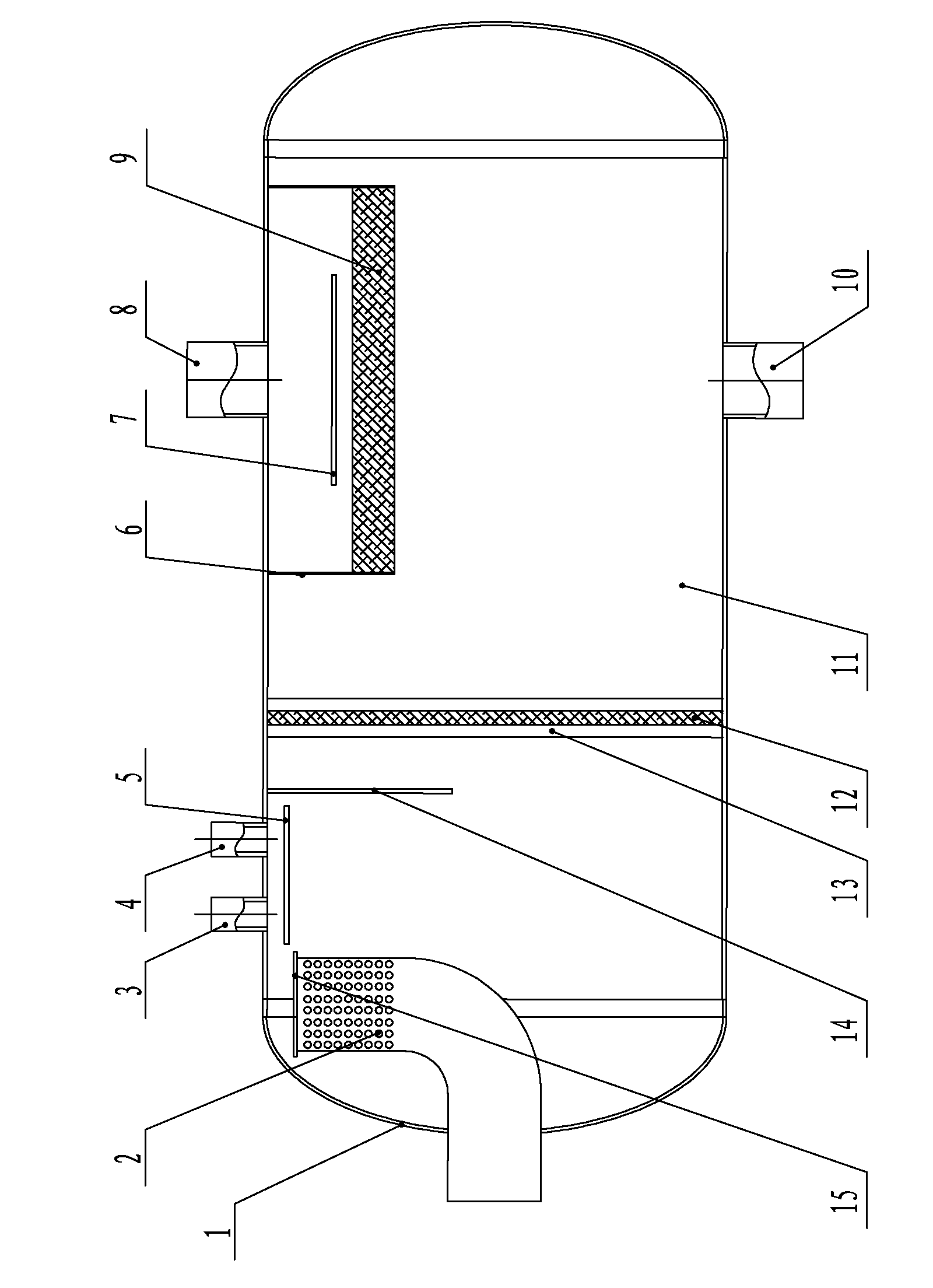
[0018] Such as figure 1 As shown: the inlet pipe 2 and the head 1 are welded deep into the interior, the direction of the inlet pipe 2 is upward, the end of the inlet pipe 2 is drilled, and the drilling area is twice the area of ​​the inlet pipe, and the port is welded with a blocking plate ; The liquid spray return port 3 and the oil cooling liquid return port 4 are welded with the shell 11 in the circumferential direction, and an anti-shock baffle 5 is added to the outlet; a distance from the anti-shock baffle 5 is welded to the right side of the baffle 14; After the plate 13 and the primary filter screen 12 are fixed, they are sealed and welded with the housing 11; the suction baffle 7 and the housing 11 are welded directly below the air outlet 8; The body 11 is sealed and welded, symmetrically installed below the gas outlet 8, the liquid outlet 10 is below the housing 11, and the gas outlet 8 is above the housing 11; the liquid inlet pipe 2, the liquid spray return port 3,...

Embodiment 2

[0021] The area of ​​the hole drilled at the end of the liquid inlet pipe 2 is three times the area of ​​the liquid inlet pipe, and the liquid spray return port 3 and the oil cooling liquid return port 4 are axially welded to the housing 11, and the others are the same as in the first embodiment.


PUM


Abstract

The invention provides a horizontal flash tank for a centrifugal unit. The horizontal flash tank comprises a head, a shell body, a liquid inlet pipe, a liquid outlet, a liquid spraying liquid return opening and an oil cooling liquid return opening. The liquid inlet pipe and the head are welded deep in the inside of the flash tank, an end opening of the liquid inlet pipe is upward, the end portion of the liquid inlet pipe is drilled, and the end opening of the liquid inlet pipe is welded through a plug plate. The liquid spraying liquid return opening and the oil cooling liquid return opening are welded to the shell body, and an opening portion is provided with an impact-resistant baffle. A baffle, a certain distance from the impact-resistant baffle, is welded close to the right side of the impact-resistant baffle. The right side of the baffle is provided with a fixing gird plate and a first-level filtering screen which are welded to the shell body. An air absorbing baffle is arranged under an air outlet and welded to the shell body. A second-level filtering demisting screen assembly is arranged under the air absorbing baffle, two sides of the second-level filtering demisting screen assembly are provided with end plates, and the end plates and the second-level filtering demisting screen assembly are welded to the shell body. The horizontal flash tank can effectively lower noise and severe fluctuation of a liquid face generated after high-speed liquid refrigerants enters the flash tank, and eliminate the phenomenon that liquid exists in gas.

Description

technical field [0001] The invention belongs to the field of mechanical manufacturing, and in particular relates to an internal structure of a central air-conditioning centrifuge unit. Background technique [0002] With the continuous and rapid development of my country's national economic construction and the rapid improvement of people's living standards, the demand for refrigeration and air conditioning with large cooling tons is increasing. Centrifugal units are characterized by large cooling capacity, low noise, high energy efficiency and reliable operation. By the majority of customers praise. [0003] The flash tank is an essential part of the centrifugal unit. The liquid refrigerant from the condenser enters the flash tank through throttling and decompression, and flashes in the flash tank to become saturated gas, and the saturated gas enters the middle of the compressor. The suction port is compressed; the liquid refrigerant formed in the flash tank is fed to the ev...

Claims


Application Information

Patent Timeline
IPC IPC(8): F25B41/00F24F13/24
Inventor 苏厚泉张万青王富华丁继龙白俊明
Owner SHANDONG GRAD GROUP
Why Eureka
Try Eureka