

A sensor assembly used for detecting rotation angle at a rotating member in a vehicle
A technology of sensor components and rotating components, which is applied in the direction of converting sensor output, using mechanical devices to transmit sensing components, and using electric/magnetic devices to transmit sensing components, etc., which can solve the problem of battery power depletion and achieve cost saving and mechanical simplified effect
- Summary
- Abstract
- Description
- Claims
- Application Information
AI Technical Summary
Problems solved by technology
Method used
Image

Examples
Embodiment Construction
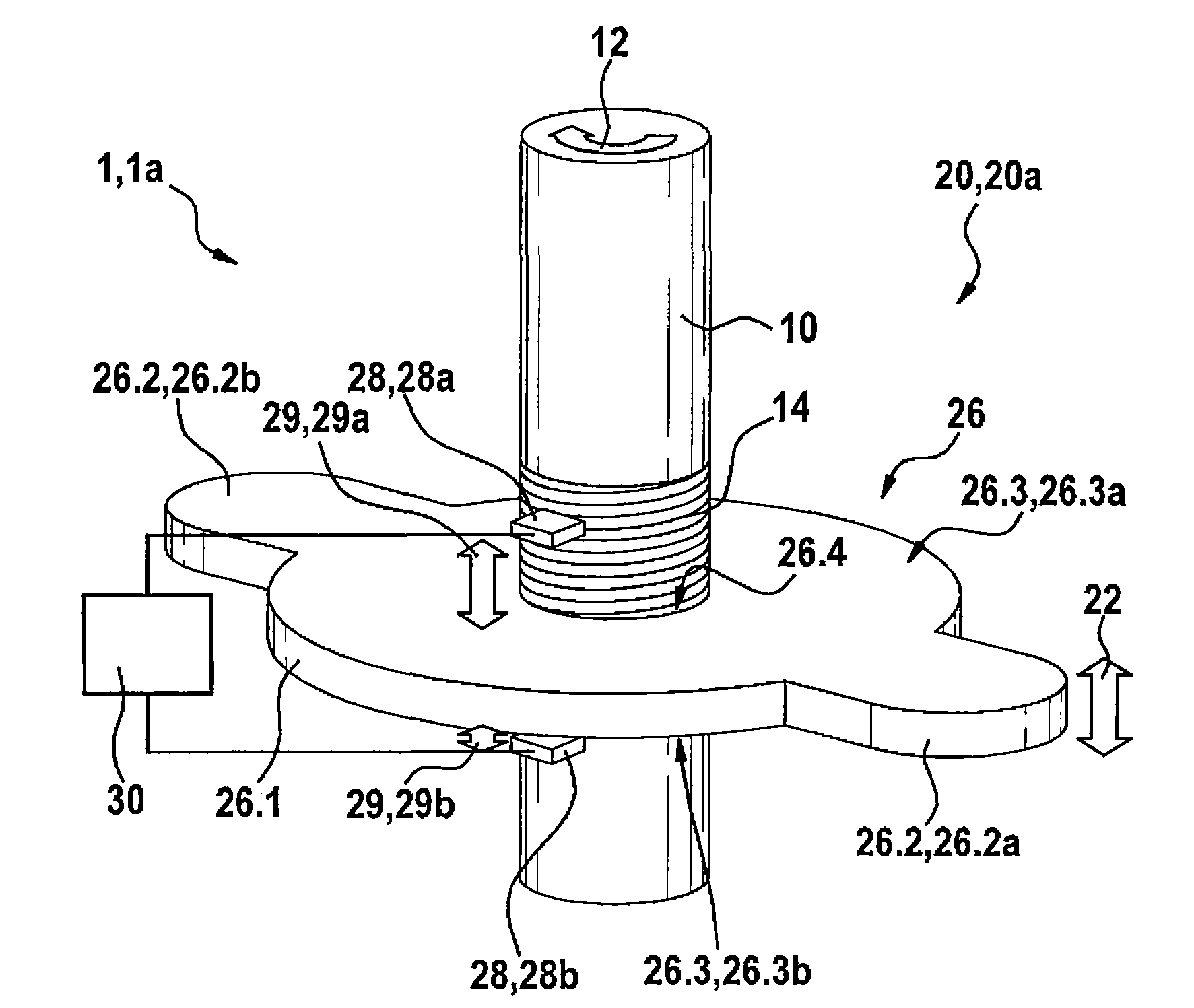
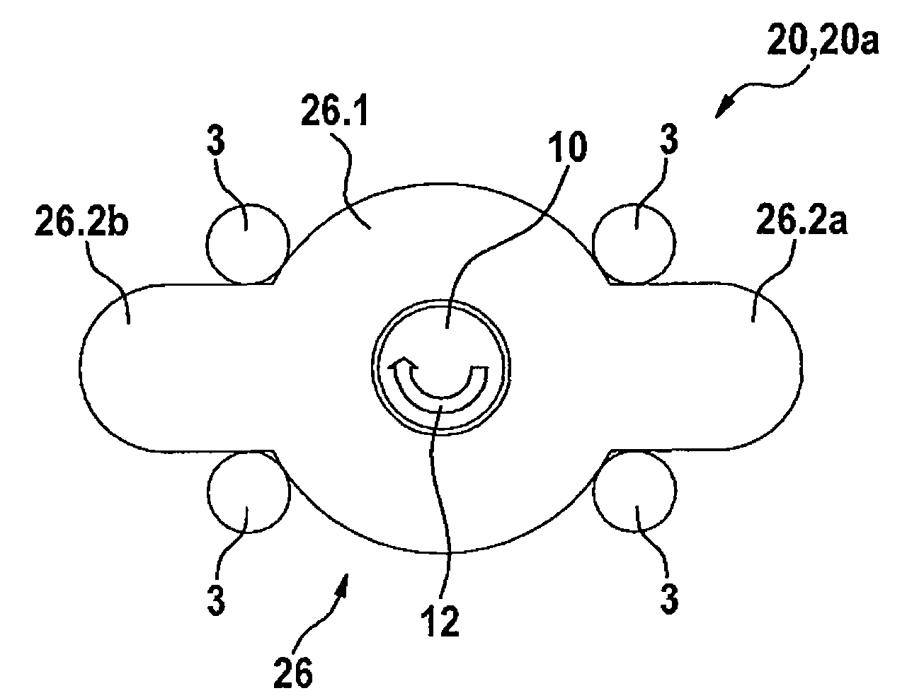
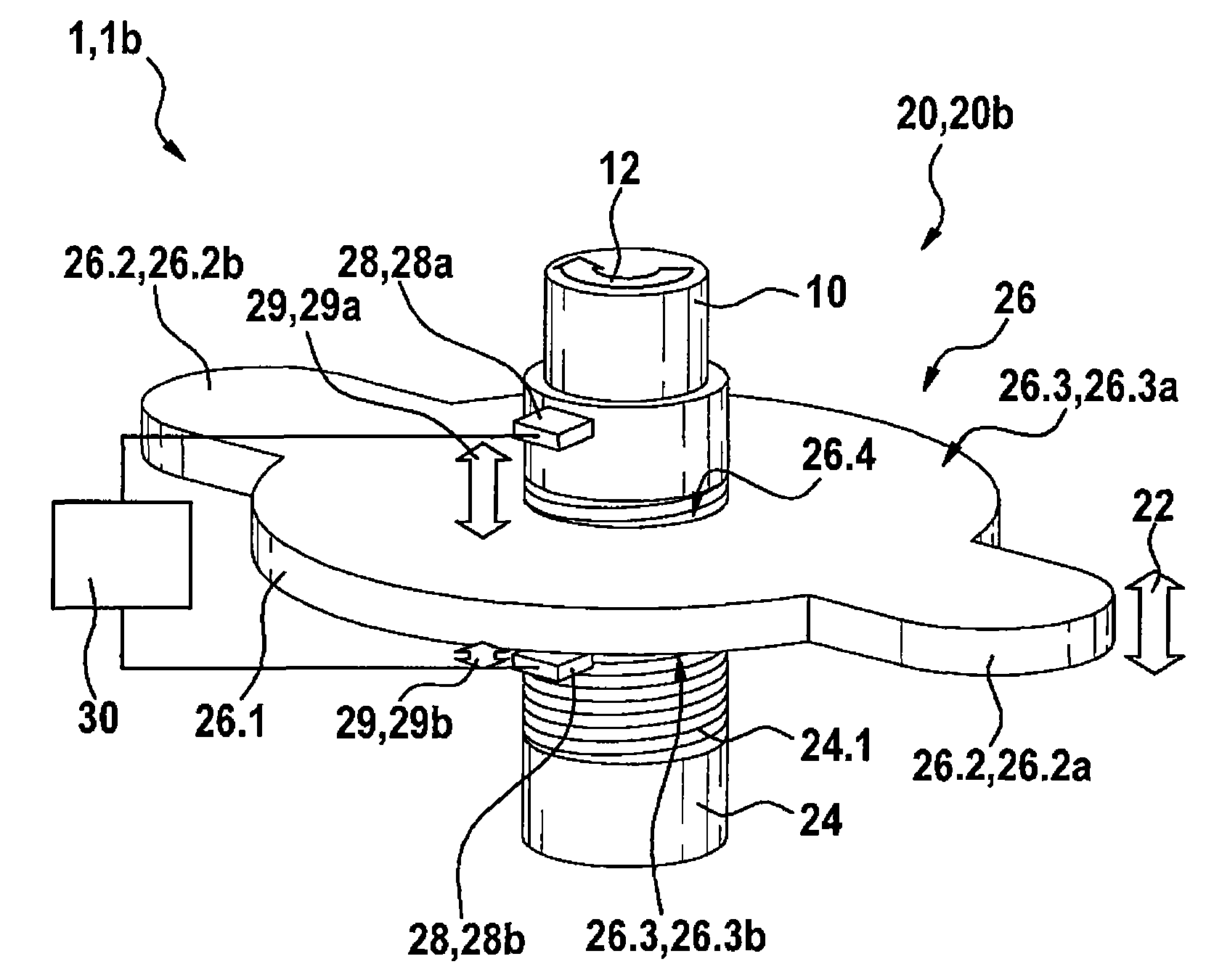
[0019] as available from Figures 1 to 3 As seen in , an embodiment of the sensor assembly 1, 1a, 1b for detecting the angle of rotation at a rotating component 10 in a vehicle according to the invention comprises a measured value indicator 26 and at least one sensor 28, 28a, 28b, the output signal of the sensor is evaluated by the evaluation and control unit 30 . The rotating member 10 is coupled to a measured value indicator 26 which, in combination with the at least one sensor 28, 28a, 28b, generates a signal representing the angle of rotation of the rotating member 10 and outputs this signal to the evaluation and control Unit 30.
[0020] According to the invention, the measured value indicator 26 is implemented together with the rotating member 10 as a motion converter 20 which converts the rotation 12 of the rotating member 10 into an axial translation 22 of the measured value indicator 26 relative to the rotating member 10 . The measured value indicator 26 here has a...
PUM
 Abstract
Description
Claims
Application Information