Exhaust gas purification device for diesel engine using heavy-oil or lower quality fuel

A diesel engine and exhaust gas technology, which is applied in the direction of exhaust devices, combustion engines, internal combustion piston engines, etc., can solve the problems of not being able to fully improve PM capture efficiency, achieve NOx reduction, suppress the formation of nitrogen oxides, and reduce The effect of combustion temperature

Inactive Publication Date: 2013-08-21
USUI KOKUSAI SANGYO KAISHA LTD
View PDF10 Cites 10 Cited by
  • Summary
  • Abstract
  • Description
  • Claims
  • Application Information

AI Technical Summary

Problems solved by technology

[0019] That is, the diesel engine exhaust gas electrical treatment method and device described in the above-mentioned Patent Document 1 has the following problems: the electrode needle 24 in the discharge charging part 22 is relatively short in the flow direction of the exhaust gas flow, and traps The plate 23 is arranged in a direction at right angles to the flow direction of the exhaust gas flow. In addition, the exhaust gas flow is in direct contact with the collecting plate 23, so the flow resistance (pressure loss: pressure loss) is relatively large; The plate 23 is thinner and the length of the flow direction of the exhaust gas flow is relatively short, so it is worried that the PM can pass through unimpeded, which cannot fully improve the possibility of PM collection efficiency; charged by corona discharge and trapped

Method used


Image

  • Exhaust gas purification device for diesel engine using heavy-oil or lower quality fuel
  • Exhaust gas purification device for diesel engine using heavy-oil or lower quality fuel
  • Exhaust gas purification device for diesel engine using heavy-oil or lower quality fuel

Examples


Embodiment 1、2

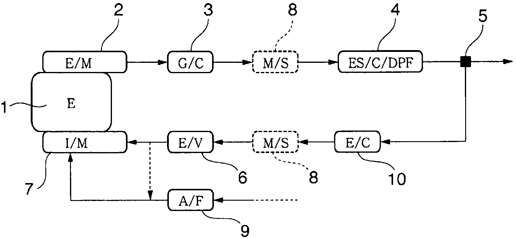
[0117] The present embodiment corresponding to the present invention 1, 2 is above-mentioned Figure 12 In the device of the twelfth embodiment shown, that is, in the exhaust gas purification device having the following structure, the temperatures of exhaust gas and EGR gas, PM, and SO are measured at positions i, i, and h. x , NO x In the above-mentioned exhaust gas purification device, the exhaust gas after the turbocharger 12 is cooled by the exhaust gas cooler 3 in advance, and then the exhaust gas purification device 4 in the electrostatic cyclone dust collector After the purification process, the EGR gas split out is processed at the scrubber 11, and then it is sent by the blower 13 through the gas-liquid separator 8, and the flow rate is controlled by the EGR valve 6 to return to the intercooler. 14 front intake pipe.

Embodiment 3、4

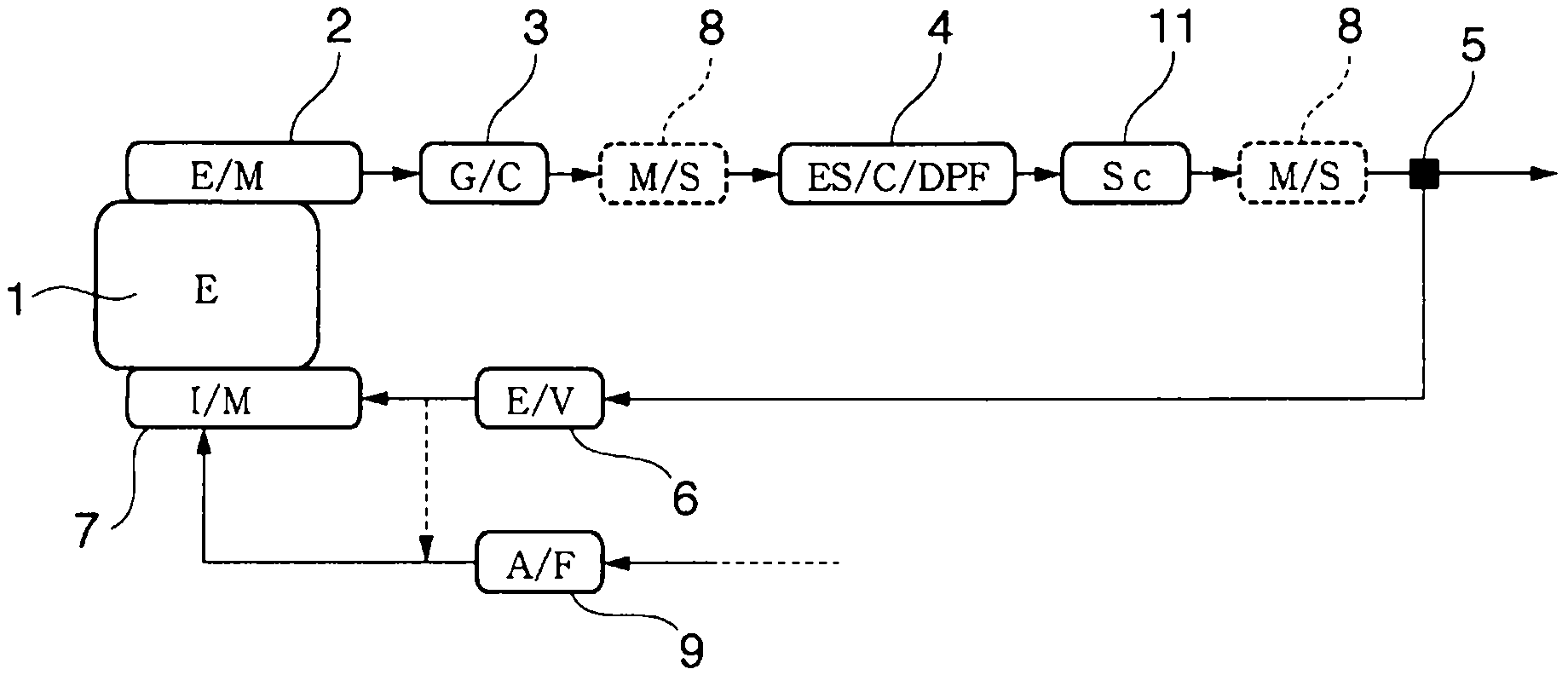
[0119] The present embodiment that is equivalent to the present invention 3,4 is above-mentioned Figure 13 In the device of the thirteenth embodiment shown, that is, the exhaust gas purifying device having the following structure, the temperatures of exhaust gas and EGR gas, PM and SO at positions 2, 4 and 1 are measured. x , NO x In the above-mentioned exhaust gas purification device, the exhaust gas after the turbocharger 12 is divided from the exhaust pipe in an untreated state to become EGR gas, and only the EGR gas is passed through the exhaust gas. The gas cooler 3, the electrostatic cyclone dust collector exhaust gas purification device 4, the scrubber 11, and the gas-liquid separator 8 are processed. After that, the EGR gas is sent by the blower 13 and controlled by the EGR valve 6 to make it return Into the intake duct before the intercooler 14.

[0120] basic features

[0121] Without exhaust gas purification device Figure 18 In the device with the structure sh...


PUM


Abstract

Provided is a diesel engine exhaust gas purification device that can remove with high efficiency PM - in particular, the SOF portion thereof or sulfate components - in the exhaust gas of a diesel engine that uses, in particular, heavy oil or an even lower quality of fuel, and that can easily and reliably suppress the emission of materials that pollute the environment or materials that impact ecosystems. The exhaust gas purification device for a diesel engine that uses heavy oil or an even lower quality of fuel is characterized by a configuration in which an exhaust gas cooler is provided to an exhaust pipe that extends to the exhaust manifold of an engine; on the downstream side of the exhaust gas cooler, an electric precipitation means is provided for removing PM contained in the exhaust gas having SOF and ISF as main components; a branching part for diverting a portion of the exhaust gas as EGR gas is provided at the downstream-side exhaust pipe of the electric precipitation means; and the EGR gas is recycled by engine air-intake via an EGR pipe that extends to the branching part and an EGR valve.

Description

technical field [0001] The present invention relates to the removal of carbon-based particulate matter (Particulate Matter: hereinafter referred to as "PM") and nitrogen oxides (hereinafter referred to as "NO") contained in the exhaust gas of a diesel engine. x ") and other harmful gases and purify the exhaust gas for ships, power generation, industrial use, etc., especially the exhaust gas treatment technology of large-displacement diesel engines using low-quality fuels below heavy oil. In more detail, it involves A purification device for exhaust gas using corona discharge in a large-displacement diesel engine that emits high-temperature exhaust gas. Background technique [0002] Diesel engines are widely used as power sources for various ships, generators, large-scale construction machinery, and various automobiles. However, the PM and NOx contained in the exhaust gas discharged from the diesel engines are well known, and not only the atmosphere pollution, but also extre...

Claims


Application Information

Patent Timeline
Patent Type & Authority Applications(China)
IPC IPC(8): F01N3/01F01N3/02F02M25/07
CPCF01N3/005F01N3/01F01N3/02F01N3/0205F01N3/04F01N13/004F01N2240/04F01N2240/22F01N2250/10F01N2260/06F01N2590/02F01N13/009F02M26/00F02M26/15F02M26/23F02M26/35Y02T10/12
Inventor 古坚宗胜牧野义泷川一仪
Owner USUI KOKUSAI SANGYO KAISHA LTD
Why Eureka
Try Eureka