
Ultrasonic flow meter

A flowmeter and ultrasonic technology, applied in the field of ultrasonic flowmeters, can solve the problems of ultrasonic signal attenuation, affecting water field changes, inaccurate measurement, etc., and achieve the effects of improving linearity, improving measurement accuracy, and improving measurement accuracy.

Inactive Publication Date: 2013-08-28
BEIJING ACCURATE ENERGY & TECH +1
View PDF6 Cites 4 Cited by
  • Summary
  • Abstract
  • Description
  • Claims
  • Application Information

AI Technical Summary

Problems solved by technology

[0010] Disadvantages: The installation of the reflector needs a bracket to fix it. Due to structural reasons, this bracket inevitably affects the linear objects in the circulating medium (such as hair, hemp used in the installation process, raw material tape, etc.) Hanging, entanglement, and jamming. If these thread-like objects are entangled on the bracket, water ripples and air bubbles will be generated on the water field in the cavity with the flow of the medium, which will seriously affect the change of the water field and cause inaccurate measurement.
[0013] Disadvantages: Restricted by the reflection angle of the transducer, it is inevitable that there is a space distance between the bottom plane of the transducer and the top plane of the square hole. In actual use, this space distance will cause air accumulation, that is, bubbles. , this phenomenon is fatal to the attenuation of the ultrasonic signal, resulting in inaccurate measurement

Method used


Image

  • Ultrasonic flow meter
  • Ultrasonic flow meter
  • Ultrasonic flow meter

Examples


Embodiment Construction

[0038] The principles and features of the present invention will be described below with reference to the accompanying drawings. The examples cited are only used to explain the present invention, and are not used to limit the scope of the present invention.

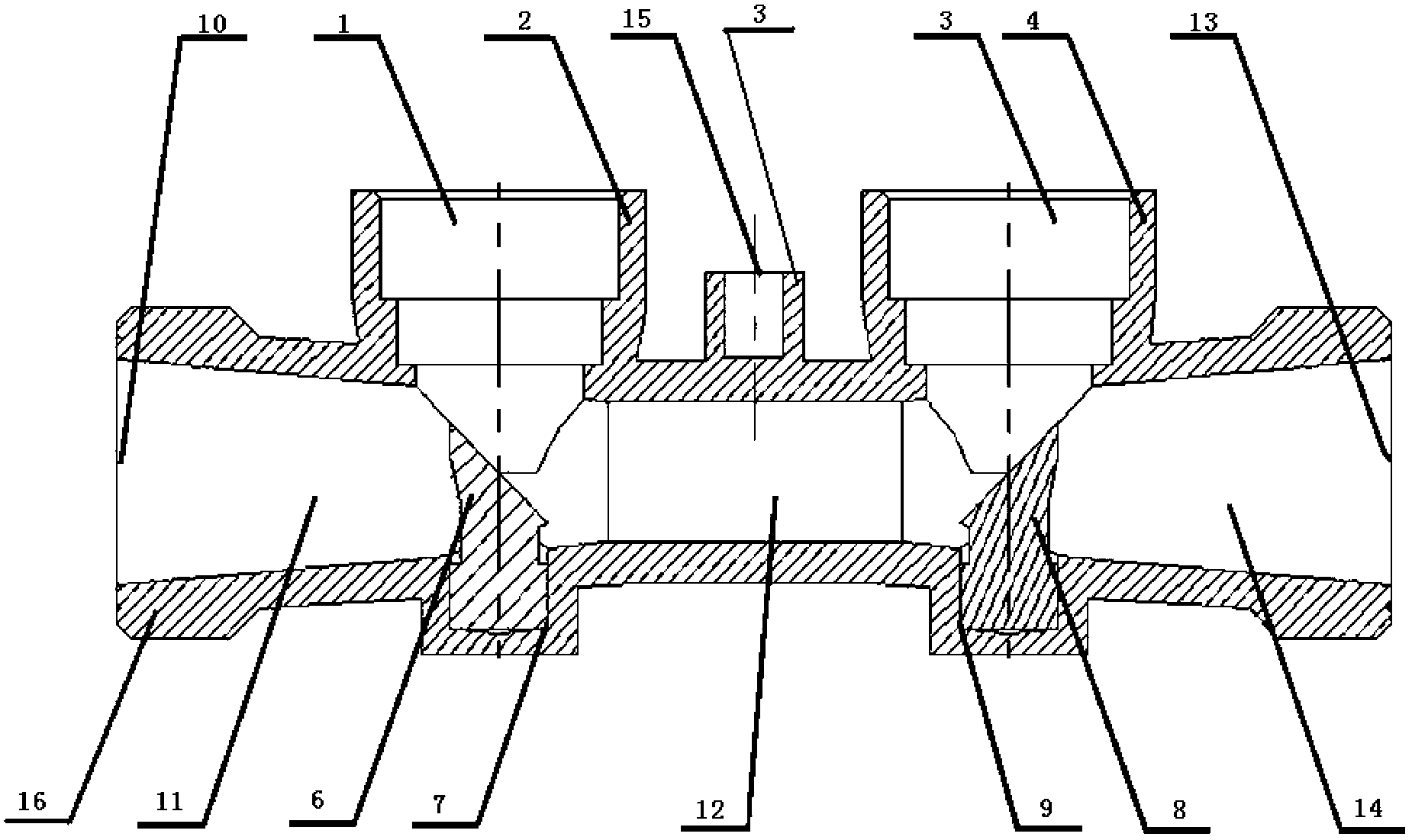
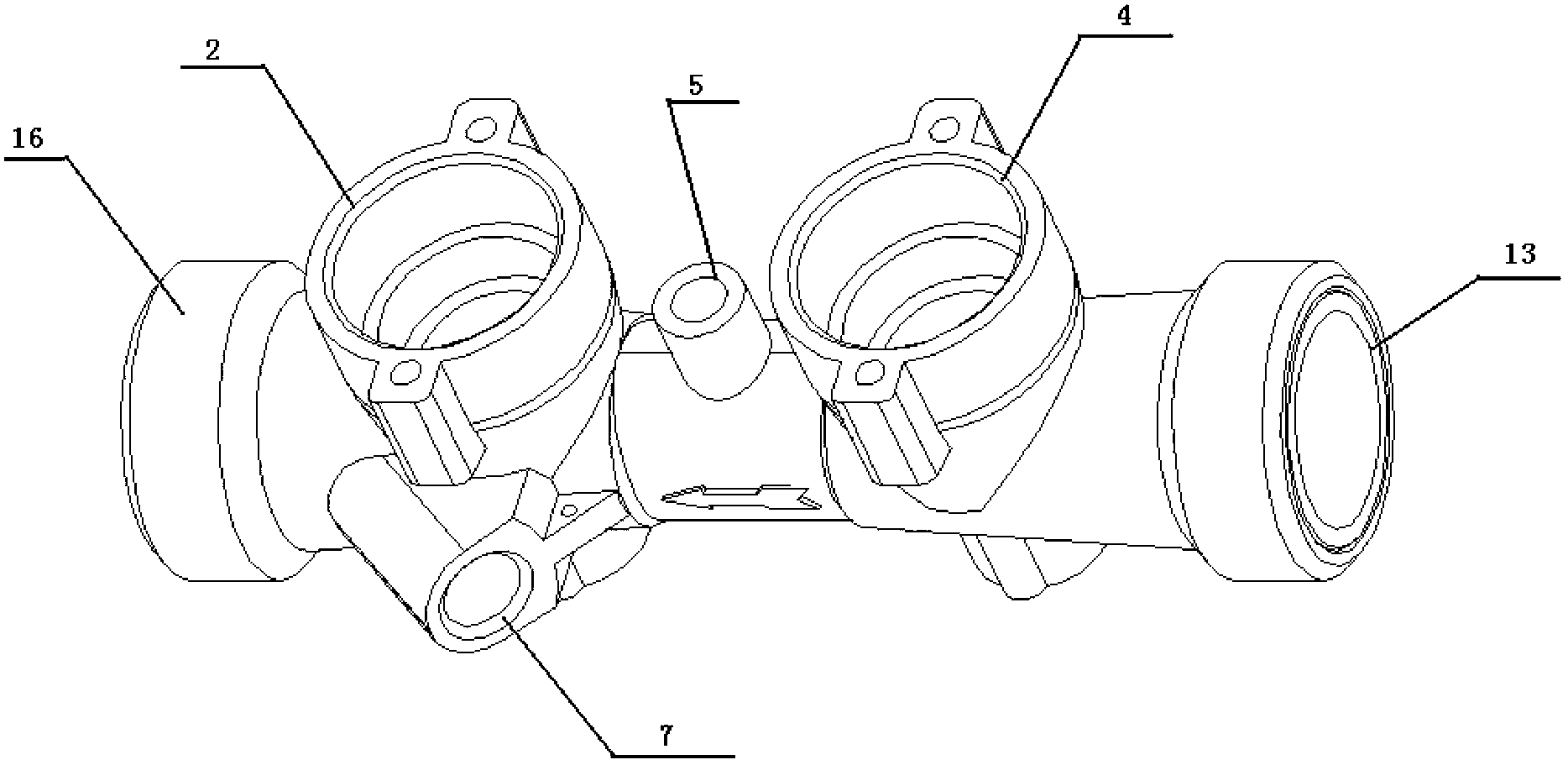
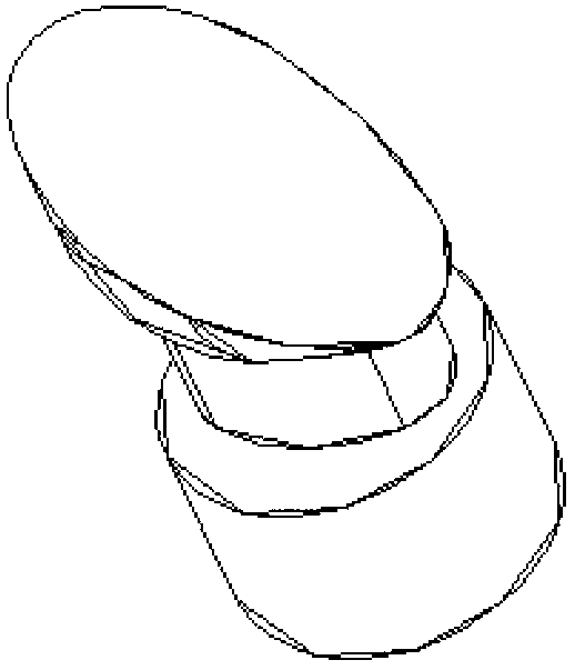
[0039] An ultrasonic flowmeter, such as figure 1 , figure 2 , image 3 , Figure 4 As shown, it includes a flow meter cavity 16, a water inlet spindle-shaped through hole 11, a flow measuring hole 12, a water outlet spindle-shaped through hole 14, a water inlet port transducer 1, a water outlet port transducer 3, and a water inlet end Ship reflection column 6 (such as image 3 , Figure 4 Shown) and ship-shaped reflecting column 8 at the outlet end (as image 3 , Figure 4 (Shown), the water inlet spindle-shaped through hole 11, the flow measuring hole 12, and the water outlet spindle-shaped through hole 14 are all located inside the flow meter cavity 16, and the water inlet spindle-shaped through hole 11, The flow measur...


PUM


Abstract

The invention relates to an ultrasonic flow meter comprising a flow meter cavity, an inflow end spindle-type straight-through hole, a flow measurement hole, an outflow end spindle-type straight-through hole, an inflow port transducer, an outflow port transducer, an inflow end ship-type reflecting column and an outflow end ship-type reflecting column. The inflow port transducer is mounted in a mounting hole of the inflow port transducer, and the outflow port transducer is mounted in a mounting hole of the outflow port transducer. The inflow end ship-type reflecting column is mounted in a mounting hole of the inflow end ship-type reflecting column, and the outflow end ship-type reflecting column is mounted in a mounting hole of the outflow end ship-type reflecting column. The inflow port transducer contacts with the inflow end ship-type reflecting column, and the outflow port transducer contacts with the outflow end ship-type reflecting column. The ultrasonic flow meter has functions of current rectification, current stabilization, blocking prevention and hanging and twisting prevention, so that a filter is not required to be mounted when the ultrasonic flow meter is used, and resources are saved for countries.

Description

Technical field [0001] The invention relates to an ultrasonic flowmeter, in particular to an ultrasonic flowmeter with a spindle-type rectifying through hole and a boat-shaped reflecting column. Background technique [0002] Ultrasonic flow sensor is mainly composed of flow meter pipe, transducer and internal reflection bracket. Among them, a pair of transducers are fixed on the inlet and backwater positions of the flowmeter pipe at a certain interval. When the measuring medium flows through the ultrasonic flowmeter, under the excitation of the external circuit, the water inlet and return water transducers alternately send and receive ultrasonic pulse signals. After being processed by the external circuit, a special chip is used to measure the ultrasonic water flow time and backwater time. The time difference is calculated by the calculator to measure the flow and velocity of the medium flowing through the pipeline. [0003] The above principles can be divided into four forms in ...

Claims


Application Information

Patent Timeline
Patent Type & Authority Applications(China)
IPC IPC(8): G01F1/66
Inventor 王军季燕飞
Owner BEIJING ACCURATE ENERGY & TECH
Learn More