Suspension suspensibility measurement apparatus and method for testing suspension suspensibility through gravity center method
A technology for measuring devices and suspensions, applied to the analysis of materials, instruments, etc., can solve the problems of many operation steps, complex operations, large test errors, etc., and achieve the effects of simple operation and calculation, accurate test data, and scientific methods
- Summary
- Abstract
- Description
- Claims
- Application Information
AI Technical Summary
Problems solved by technology
Method used
Image
Examples
Embodiment 1
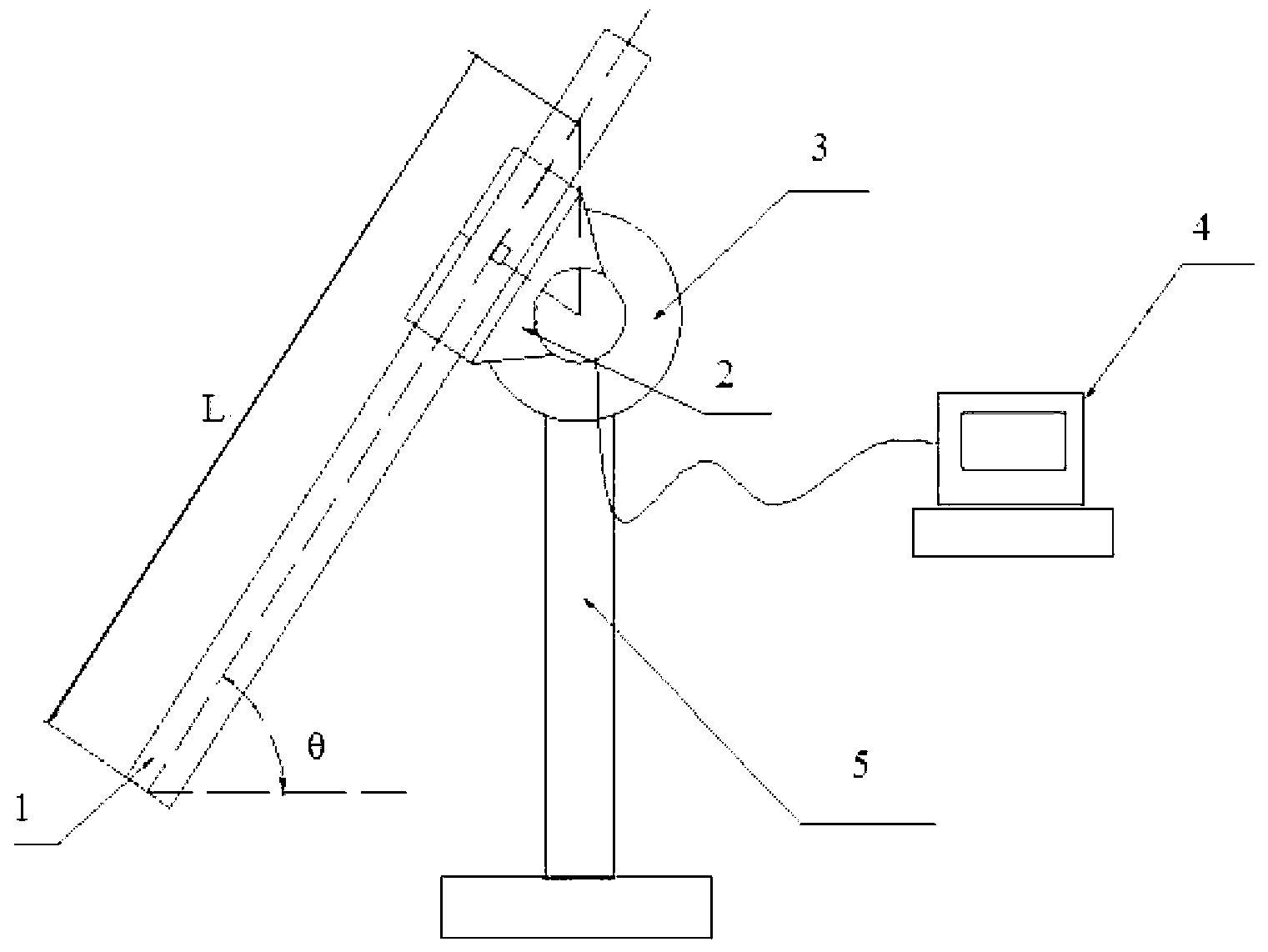
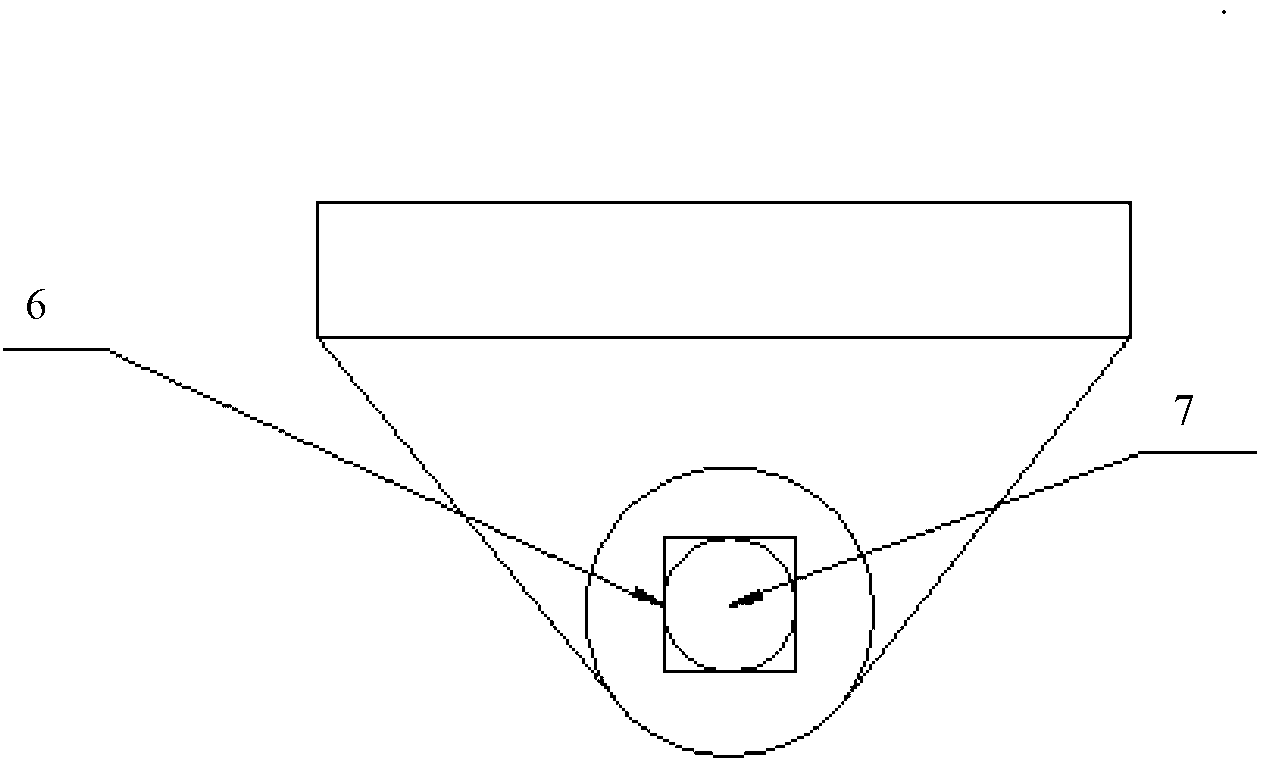
[0042]Embodiment 1, a kind of suspensibility measuring device of suspension, structure such as figure 1 As shown, the device includes a test container 1, a clamp 2, a torque sensor 3, a microcomputer 4, and a support 5; the torque sensor 3 is connected to the microcomputer 4; the clamp 2 is tight on any position on the test container 1; the clamp 2 has A joint 6 connected with the torque sensor to achieve a spline connection. The magnet 7 is embedded in the joint 6 to make the clamp joint and the test end 8 of the torque sensor magnetically tightened. The torque sensor 3 is fixed on the bracket 5, and the central axis is parallel to the horizontal plane , perpendicular to the center line of the length direction of the test container, and make the test container form an angle θ with the horizontal plane, θ=10~85°.
Embodiment 2
[0043] Embodiment 2, suspension performance test method of suspension
[0044] Suspension used for testing: high-radiation and energy-saving coatings, the main components are zirconia, SiC, refractory clay, bentonite and other powders dispersed in carboxymethyl cellulose, water glass, and suspension formed in water, with a bulk density of 1.45g / cm 3 .
[0045] Suspension performance testing device is as in Example 1. Suspension performance test method, the steps are as follows:
[0046] Connect the torque sensor 3 and the microcomputer 4 information collection system, clamp the test container 1 with the clamp 2;
[0047] Connect the fixture joint 6 with the test end 8 of the torque sensor, so that the center axis of the test end of the torque sensor is parallel to the horizontal plane and perpendicular to the center line of the test container; the intersection point of the center line of the test container in the length direction and the plane perpendicular to the horizontal...
PUM
 Abstract
Description
Claims
Application Information
 - R&D
- Intellectual Property
- Life Sciences
- Materials
- Tech Scout
- Unparalleled Data Quality
- Higher Quality Content
- 60% Fewer Hallucinations
Browse by: Latest US Patents, China's latest patents, Technical Efficacy Thesaurus, Application Domain, Technology Topic, Popular Technical Reports.
© 2025 PatSnap. All rights reserved.Legal|Privacy policy|Modern Slavery Act Transparency Statement|Sitemap|About US| Contact US: help@patsnap.com


