Clock recovery circuit through NFC active load modulation based on digital phase-locked loop
A technology of clock recovery and active load, applied in the direction of automatic power control, electrical components, etc., can solve problems such as frequency error and achieve the effect of reducing frequency difference
Inactive Publication Date: 2013-08-28
SHANGHAI QUANRAY ELECTRONICS
View PDF6 Cites 39 Cited by
- Summary
- Abstract
- Description
- Claims
- Application Information
AI Technical Summary
Problems solved by technology
However, when the phase-locked loop with large bandwidth is converted from closed-loop to open-loop, it will introduce a large frequency error (caused by the charge injection of the switch, etc.), so t
Method used
View moreImage
Smart ImageViewing Examples

Examples
 PUM
 Abstract
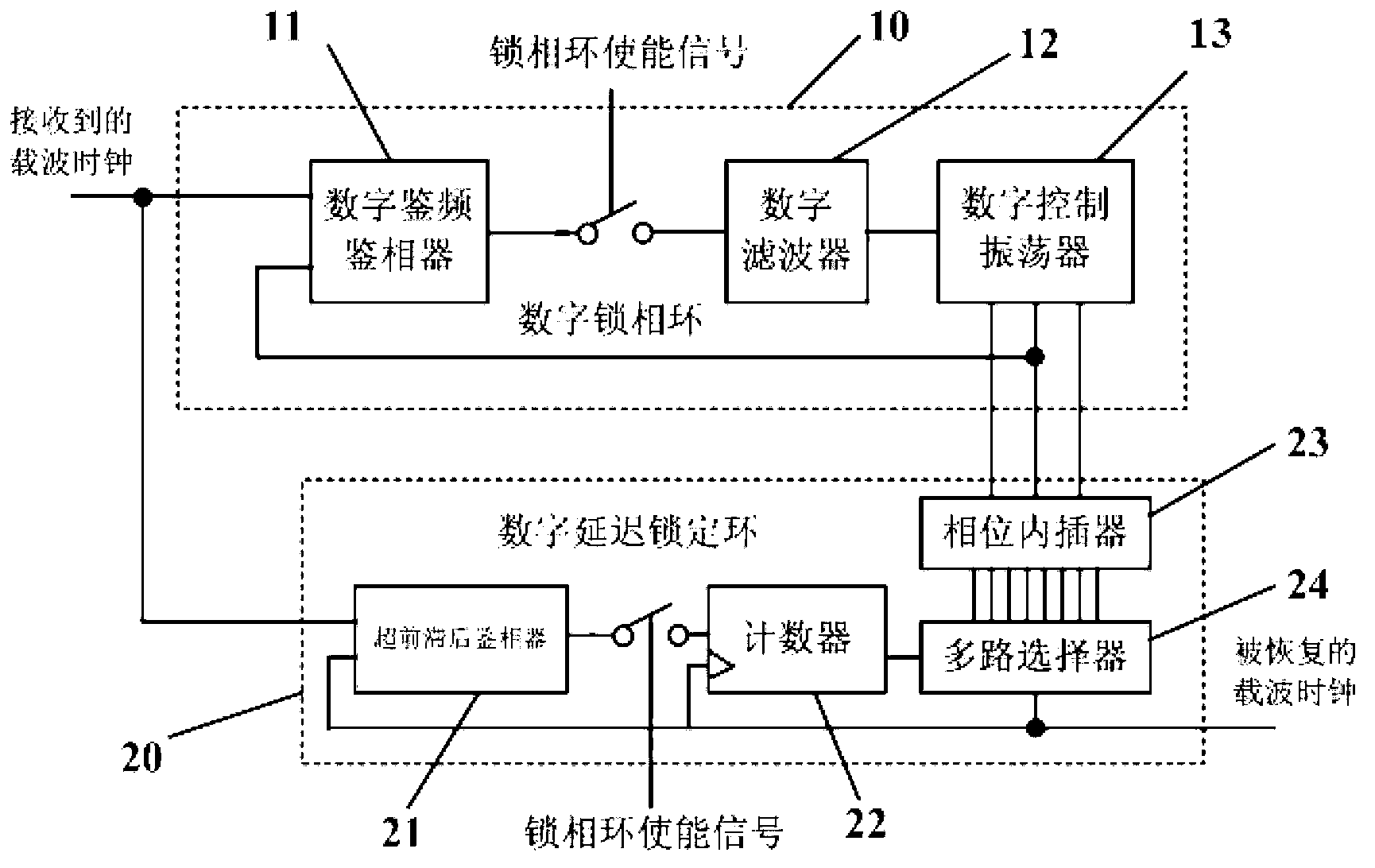
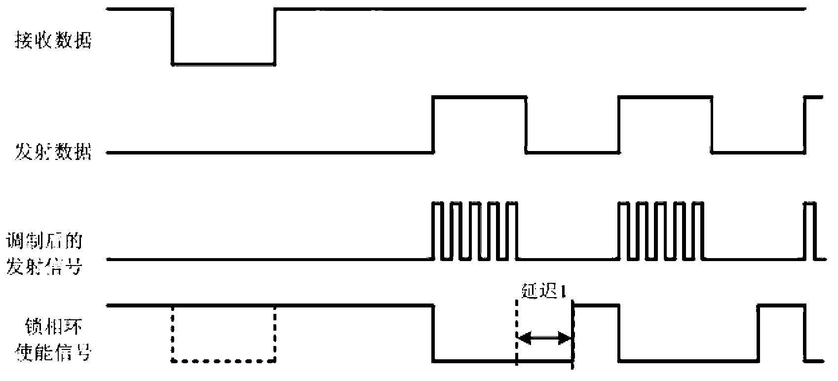
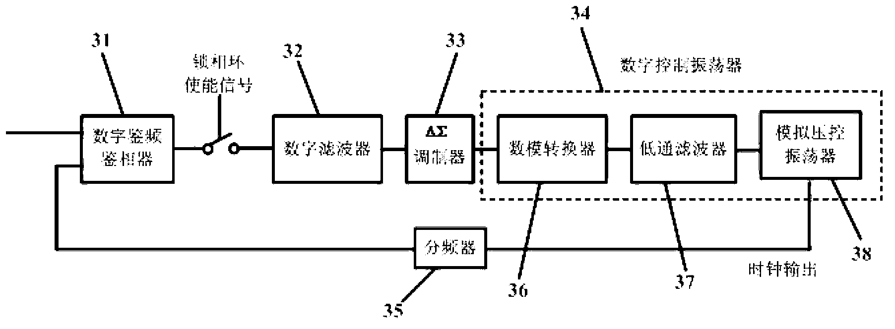
A clock recovery circuit through NFC active load modulation based on a digital phase-locked loop is formed by a digital phase-locked loop and a digital delay locking loop. The digital phase-locked loop works under a tracking carrier frequency mode and a fixed oscillation frequency mode. Under the fixed oscillation frequency mode, oscillation frequency is formed and locked in the period of tracking a carrier wave, the digital phase-locked loop is an all-digital structure phase-locked loop, and the digital delay locking loop receives a split phase clock of the phase-locked loop, and fast locks a clock which is closest to a carrier phase through comparison with a phase of the carrier wave. The digital delay locking loop works under a phase tracking mode and a fixed phase mode, under the fixed phase mode, the digital delay locking loop constantly outputs the same split phase clock, and the clock is obtained under a tracking mode. The clock recovery circuit reduces frequency difference caused by injecting noise in the time of conversion from a closed loop to an open loop, enables bandwidth of the phase-locked loop to be reduced to further lower phase noise, and can avoid the situation that the phase difference cannot be corrected due to the fact that the bandwidth is reduced.
Description
technical field [0001] The invention relates to the technical field of active transmission of Near-field-communication (hereinafter referred to as NFC), in particular to a clock recovery circuit for NFC active load modulation based on a digital phase loop. Background technique [0002] Passive or active load modulation is generally used in NFC to achieve data return from the contactless card to the reader. Passive load modulation transmits data by changing the antenna impedance of the contactless card, while active load modulation transmits data equivalent to the passive mode by intermittently actively transmitting an alternating electric field with the same frequency as the carrier of the reader. Purpose. Compared with passive mode, active load modulation has longer communication distance and stronger ability to resist metal shielding. [0003] In order to achieve the maximum communication distance, the alternating electric field emitted by the active load modulation need...
Claims
Login to View More Application Information
Patent Timeline
 IPC IPC(8): H03L7/085H03L7/18
Inventor 沈仲汉
Owner SHANGHAI QUANRAY ELECTRONICS