Compressed air supply installation, pneumatic system and method for operating a pneumatic installation

A technology for compressed air and pneumatic equipment, applied in the field of vehicle air spring equipment and pneumatic systems, and can solve problems such as feasibility limitations

Active Publication Date: 2013-08-28
ZF CV SYST EURO BV
View PDF18 Cites 11 Cited by
  • Summary
  • Abstract
  • Description
  • Claims
  • Application Information

AI Technical Summary

Problems solved by technology

But especially for further applications, which require a more flexible and fast manipulation of compressed air in s

Method used


Image

  • Compressed air supply installation, pneumatic system and method for operating a pneumatic installation
  • Compressed air supply installation, pneumatic system and method for operating a pneumatic installation
  • Compressed air supply installation, pneumatic system and method for operating a pneumatic installation

Examples


Embodiment Construction

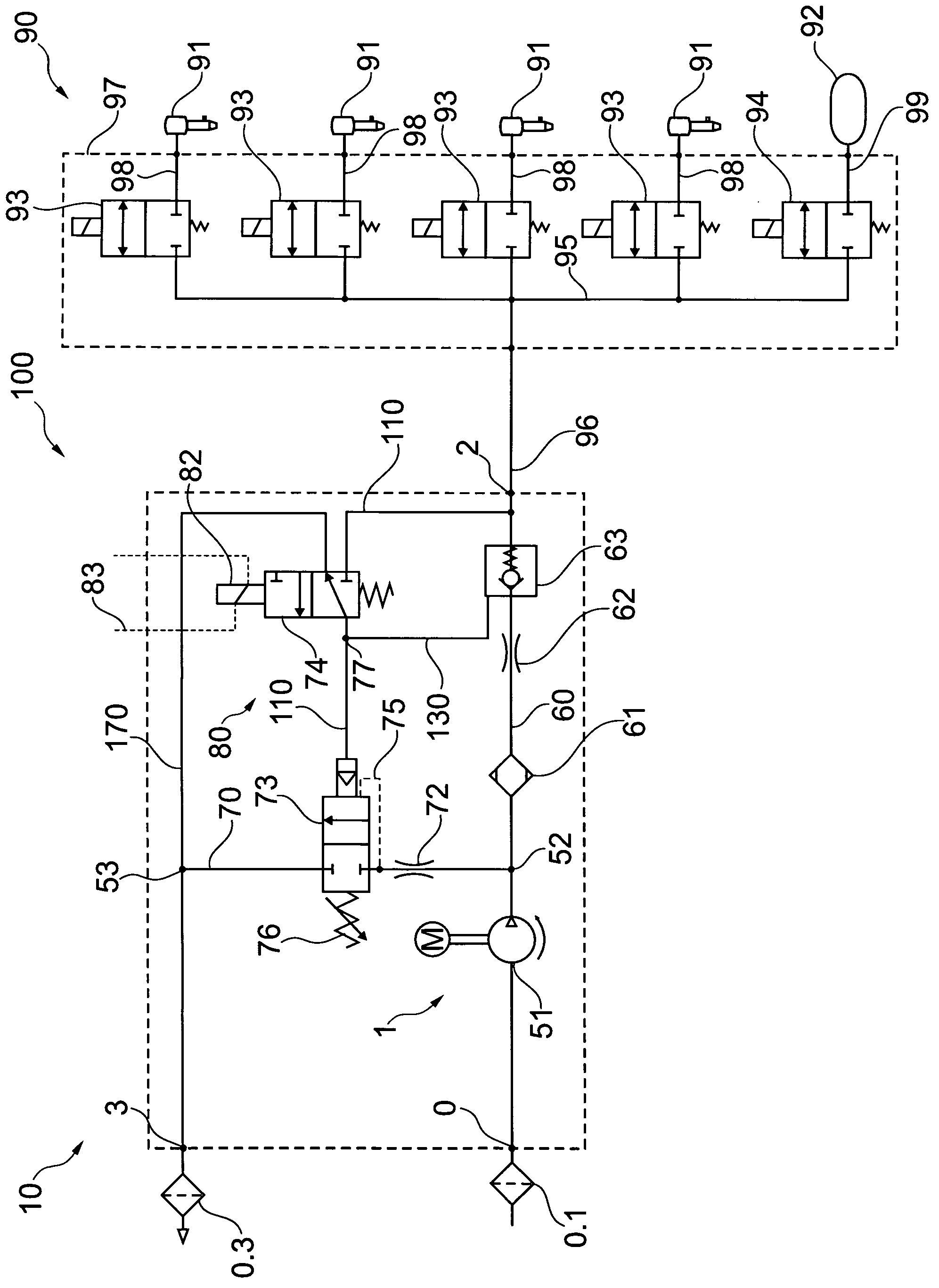
[0108] figure 1 A pneumatic system 100 is shown with a compressed air supply device 10 and a pneumatic device 90 in the form of an air spring device. In this case, the air spring arrangement has four so-called bellows 91 which are each associated with a wheel of the vehicle (not shown in detail) and form the air springs of the vehicle. Furthermore, the air spring device has a storage device 92 for storing rapidly available compressed air for the bellows 91 . Arranged upstream of the bellows 91 in each spring branch line 98 is a solenoid valve 93 , which in each case serves as a level regulating valve for opening or closing the air spring formed by the bellows 91 . The solenoid valve 93 in the spring branch line 98 is designed as a 2 / 2-way valve. A solenoid valve 94 in the form of a further 2 / 2-way valve is arranged upstream of the accumulator 92 as an accumulator valve in the accumulator branch line 99 . The solenoid valves 93 , 94 are connected by means of spring branch l...


PUM


Abstract

The invention relates to a compressed air supply installation (10, 11, 12, 20, 30) for operating a pneumatic installation (90), especially an air suspension installation of a vehicle, comprising a compressed air supply unit (1), a compressed air port (2) towards the pneumatic installation (90), a venting port (3) towards the surroundings, a first pneumatic connection between the compressed air supply (1) and the compressed air port (2), said pneumatic connection having an air drier (61) and a shut-off valve, and a second pneumatic connection between the compressed air port (2) and the venting port (3). According to the invention, the shut-off valve is designed as a pneumatically pilot-controlled check valve (63, 64).

Description

technical field [0001] The invention relates to a compressed air supply installation according to the preamble of claim 1 . Furthermore, the invention relates to a pneumatic system with such a compressed air supply. The invention also relates to a method according to the preamble of claim 19 for operating a pneumatic installation, in particular an air spring installation of a vehicle. Background technique [0002] Compressed air supply systems are used in all types of vehicles, in particular for supplying compressed air to the air spring system of the vehicle. The air spring system can also include a level adjustment device with which the distance between the axle and the body can be adjusted. The air spring device of the pneumatic system mentioned at the beginning of this article consists of several air bellows pneumatically connected on a common line (channel Galerie), which can lift the body with increasing inflation, and correspondingly with The ever-decreasing inflat...

Claims


Application Information

Patent Timeline
IPC IPC(8): F15B21/04B60G17/052F15B21/044F15B21/048
CPCF15B21/044F15B21/048F15B2211/30505F15B2211/3059F15B2211/31564F15B2211/655F15B2211/8855B60G17/0523Y10T137/0318Y10T137/3087F15B13/022G05D16/06B60G2500/205B60T17/004B60G2500/2021B60T17/04B60G2500/203B60T17/02Y10T137/87193Y10T137/2589Y10T137/7782Y10T137/7876
Inventor 迪特尔·弗兰克弗兰克·迈斯纳乌韦·施塔贝诺
Owner ZF CV SYST EURO BV
Why Eureka
Try Eureka