
Ultrasonic flowmeter

An ultrasonic and flowmeter technology, applied in the direction of volume measurement, flow measurement/mass flow, liquid/fluid solid measurement, etc., can solve problems such as complex structure, increased time resolution, and adverse effects of flow coefficient flatness

Inactive Publication Date: 2013-08-28
PANASONIC CORP
View PDF9 Cites 10 Cited by
  • Summary
  • Abstract
  • Description
  • Claims
  • Application Information

AI Technical Summary

Problems solved by technology

[0007] However, when the flow velocity ratio of each layer differs depending on the measured flow rate as described above, it will adversely affect the flatness of the flow coefficient.
[0008] In particular, in the case of a V-shaped propagation path that utilizes wall reflection of ultrasonic waves, the distance that ultrasonic waves propagate in the flow path is twice that of the case without reflection, which has the advantage of improving the time resolution during measurement. , but is more affected by the flow difference between layers
[0009] In order to reduce this effect, conventional measures have been taken to provide a straightening member at the inlet of the measurement channel to make the flow uniform. However, the installation of the straightening member has caused problems such as a complicated structure and an increase in cost.

Method used


Image

  • Ultrasonic flowmeter
  • Ultrasonic flowmeter
  • Ultrasonic flowmeter

Examples


Embodiment approach 1

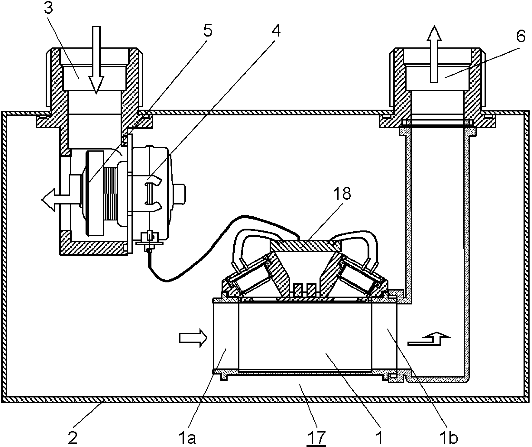
[0026] Such as figure 1 As shown, a shutoff valve 5 is provided in the middle of the fluid supply path 3, and the shutoff valve 5 is opened and closed by a valve body that cooperates with a drive unit 4 using an electromagnetic device such as a stepping motor. The hollow arrow indicates the flow direction of the fluid to be measured, and the fluid to be measured flows out from the fluid supply channel 3 to the inside of the measuring device housing 2 when the valve is in an open state. The measurement channel 1 is a rectangle with a rectangular cross section. The fluid to be measured that fills the inside of the measuring device case 2 flows into the measuring flow path 1 from the upstream side 1a that is the inlet side of the measuring flow path 1, and flows into the measuring device case 2 via the fluid outflow path 6 connected to the downstream side 1b. external outflow.

[0027] In addition, the shutoff valve 5 is closed when an abnormality occurs in the fluid flow, an ...


PUM


Abstract

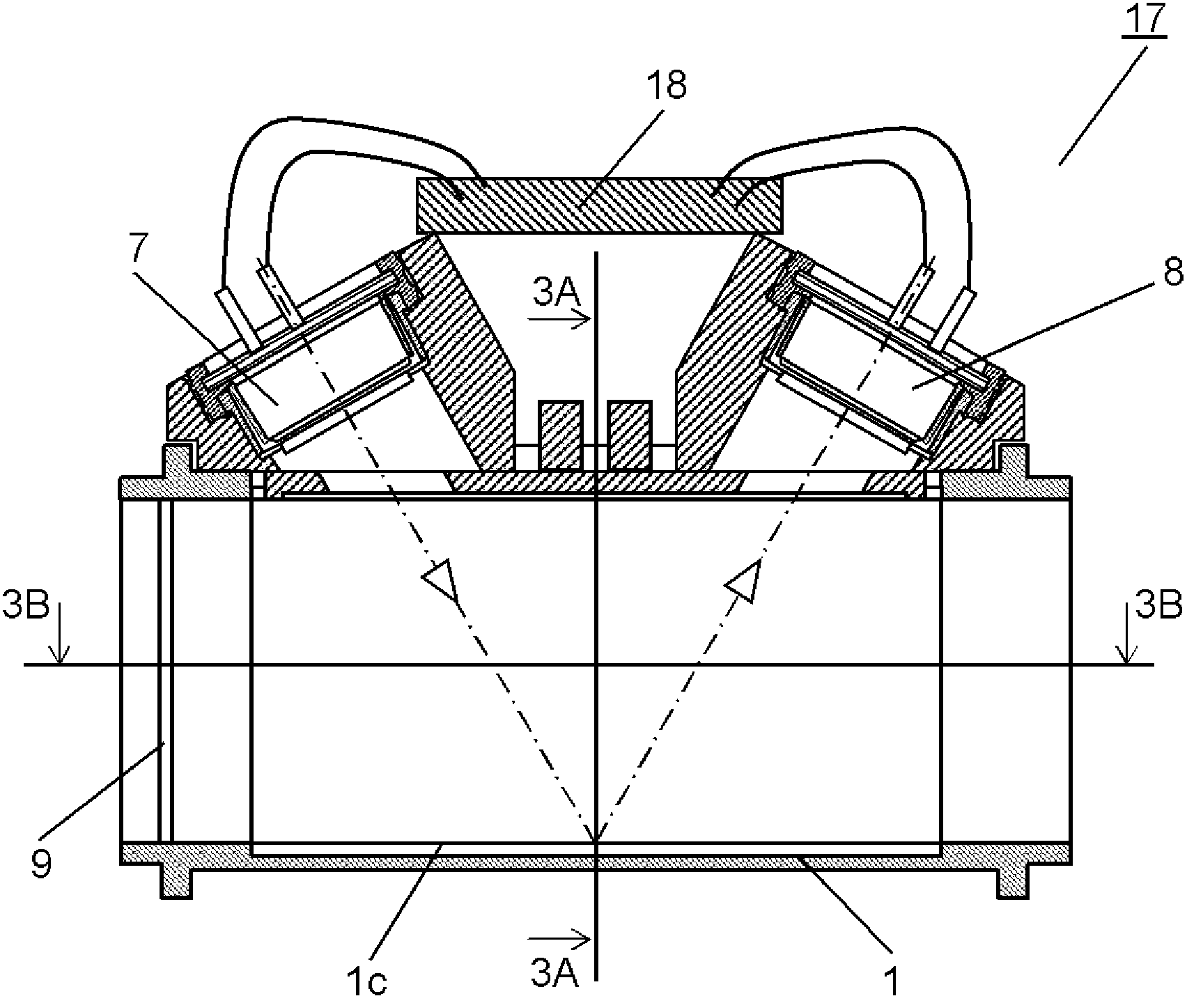
The present invention is configured to detect a flow volume by means of a measuring flow channel (1) composed of layer-like flow channels, and a pair of ultrasonic sensors (7, 8), which are disposed on the same wall surface side of the measuring flow channel (1) such that an ultrasonic wave propagation path using reflection on the flow channel inner wall surface (1c) on the facing side is configured. A control rod (9), i.e., a fluid control means, is disposed at the front in the upstream of partitioning plates, said partitioning plates constituting a multilayer section.

Description

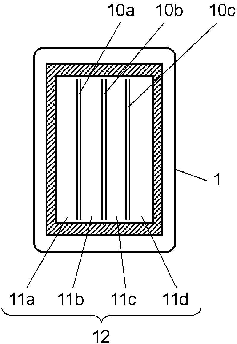
technical field [0001] The present invention relates to an ultrasonic flowmeter for measuring the flow rate of gas or the like. Background technique [0002] Such as Figure 8 As shown, the conventional ultrasonic flowmeter of this type is equipped with a flow velocity detection unit, which is composed of a pair of ultrasonic transmitter receivers (not shown) arranged oppositely upstream and downstream of the measurement flow path 15. The measurement flow path The upstream side of 15 is connected to the fluid supply path 13 , and the downstream side is connected to the fluid outflow path 14 . [0003] In addition, the inside of the measurement channel 15 is divided using a plurality of flat partitions 16 so that the fluid forms a laminar flow. [0004] The flow velocity detection means measures the flow velocity of the fluid flowing through the measurement channel 15 based on the propagation time of ultrasonic waves between the ultrasonic transmitters and calculates the flo...

Claims


Application Information

Patent Timeline
Patent Type & Authority Applications(China)
IPC IPC(8): G01F1/66G01F1/00
CPCG01F1/66G01F1/662G01F15/00
Inventor 宫田肇中野慎藤井裕史尾崎行则
Owner PANASONIC CORP
Learn More