Shield conductor

A technology for shielding conductors and shielding parts is applied in the field of shielding conductors, which can solve the problems of ineffective use of space to arrange shielded conductors, and achieve the effect of effective arrangement.

Inactive Publication Date: 2013-08-28
AUTONETWORKS TECH LTD +2
View PDF7 Cites 3 Cited by
  • Summary
  • Abstract
  • Description
  • Claims
  • Application Information

AI Technical Summary

Problems solved by technology

Therefore, the traditional technology has the problem of not being able to effectively utilize the space for arranging shielded conductors

Method used


Image

  • Shield conductor
  • Shield conductor
  • Shield conductor

Examples


no. 1 example

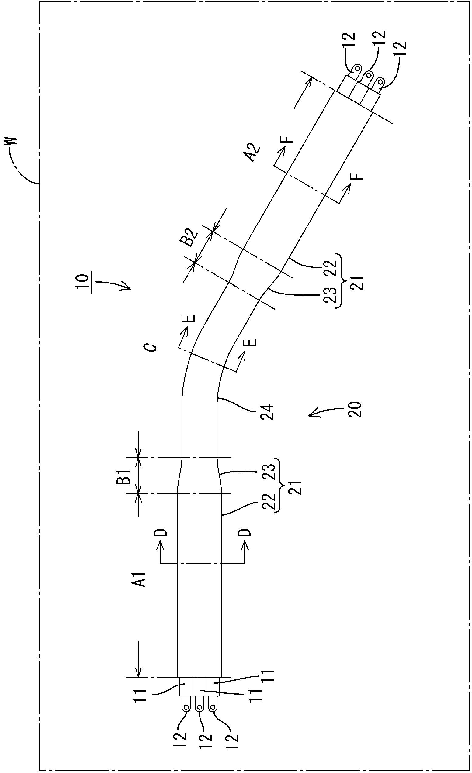
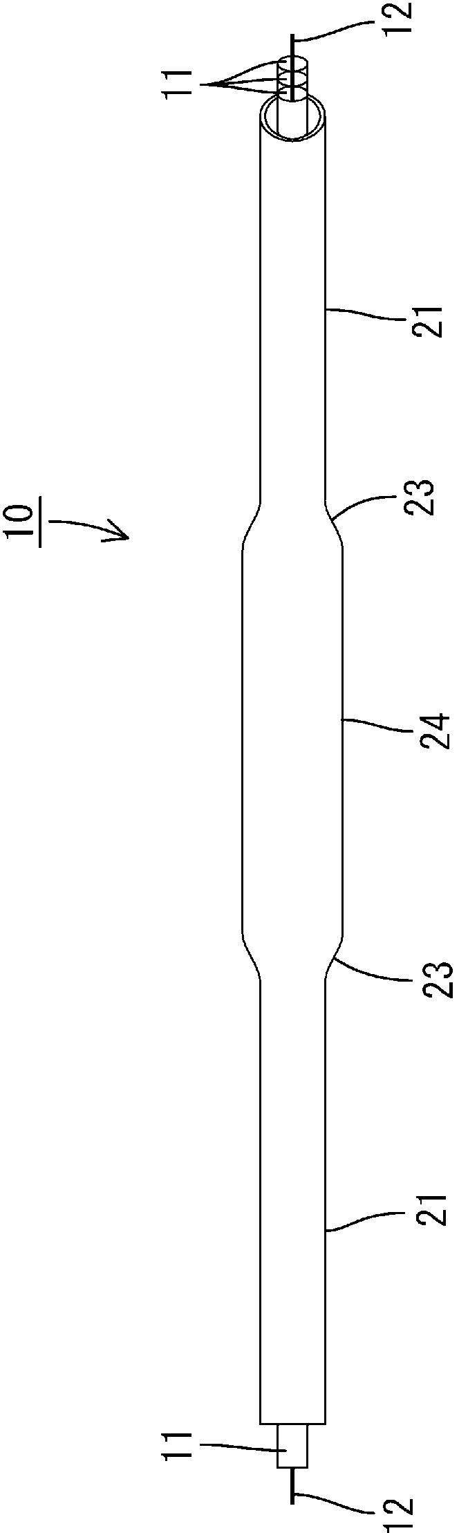
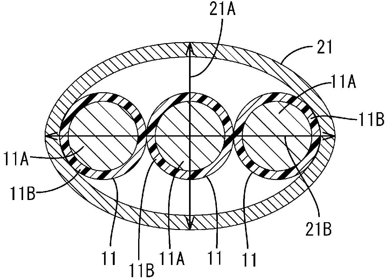
[0049] refer to Figure 1 to Figure 7 A first embodiment of the present invention is described. The shield conductor 10 of this embodiment is routed between devices in a power source including a battery, an inverter, and a motor (not shown) for driving an electric vehicle. The shield conductor 10 arranged between the battery and the inverter includes two electric wires 11 . The shield conductor 10 arranged between the inverter and the motor includes three electric wires 11 . In the following description, the shielded conductor 10 which includes three electric wires 11 and which is arranged (or wired) under the floor of the vehicle W between the inverter and the motor will be described. In this manual, figure 1 The left and right lower sides in are defined as the front and rear sides, respectively. compared to figure 2 And limit the top-bottom direction.

[0050] Such as figure 1 As shown, the shielded conductor 10 includes three wires 11 and a tube 20 . The wire 11 pa...

no. 2 example

[0082] will refer to Figure 8 with Figure 9 A second embodiment of the present invention is described. The same components as those in the above-described embodiment will be denoted by the same reference numerals and will not be explained.

[0083] In the second embodiment, the outer circumference of the shielded conductor 10 is covered by a heat shrinkable tube 40, such as Figure 8 shown. Such as Figure 9 As shown, the shielded conductor 10 is inserted into the heat shrinkable tube 40, and then the heat shrinkable tube 40 is heated to shrink it. As a result, the heat-shrinkable tube 40 is tightly attached to the outer peripheral surface of the tube 20 .

[0084] Since the heat-shrinkable tube 40 is tightly adhered to the outer circumference of the tube 20 , the outer circumference of the tube 20 is protected by the heat-shrinkable tube 40 .

no. 3 example

[0086] will refer to Figure 10 A third embodiment of the present invention is described. The same components as those in the above-described embodiment will be denoted by the same reference numerals and will not be explained. The tube 20 according to the above-described embodiment is made of a material such as aluminum alloy. In a third embodiment, the tube 50 is made of a cladding material comprising a first element 51 on the inner side and a second element 52 on the outer side, as Figure 10 Hierarchical settings are shown.

[0087] The first member 51 is made of aluminum or an aluminum alloy. The second element 52 is made of iron or an iron alloy.

[0088] The braided wire 53 includes a tinned copper alloy wire. At the end of the tube 50 , a braided wire 53 covers the outer circumference of the second element 52 . At the end of the tube 50 (on the end of the second member 52 of the tube 50 ) the tube 50 and the braided wire 53 are connected by means of connection suc...


PUM


Abstract

A shield conductor (10) is provided with: a metal pipe (20); electrical wires (11) running through said pipe (20); first irregularly shaped sections (21) that are provided in the pipe (20) and each have a first narrow section (21A) and a first wide section (21B) having different outside diameters; and a second irregularly shaped section (24) that is formed in the pipe (20) at a lengthwise position different from that of the first irregularly shaped sections (21) and has a second narrow section (24A) and a second wide section (24B) having different outside diameters. The first narrow section (21A) and the second narrow section (24A) are formed at different points along the circumference of the pipe, as are the first wide section (21B) and the second wide section (24B).

Description

technical field [0001] The invention relates to a shielding conductor. Background technique [0002] Shielded conductors with shielding function are used in interconnection devices such as inverters, motors and batteries in hybrid and electric vehicles. [0003] As described in Patent Document 1, such a shield conductor may include a plurality of electric wires and a metal pipe bent along a wiring path. The wires are housed in a tube with a circular periphery. [0004] Patent Document 1: Japanese Unexamined Patent Publication 2004-171952 Contents of the invention [0005] There is a need to arrange shielding conductors efficiently using space for installing shielding conductors in vehicles. More specifically, when a metal pipe having a circular outer circumference is arranged under the floor of a vehicle, the space under the floor needs to be at least as high as the outer diameter of the metal pipe. There is a height restriction on the space below the floor, so a high ...

Claims


Application Information

Patent Timeline
Patent Type & Authority Applications(China)
IPC IPC(8): H01B7/17H01B7/08H01B7/20H01B7/22H05K9/00
CPCB60R16/0215H02G3/0462H01B7/08H01B7/17H01B7/20H01B7/22H01B7/16
Inventor 青山直树桑原正纪园田不二夫井谷康志杉本佳典伊泽克俊
Owner AUTONETWORKS TECH LTD
Why Eureka
Try Eureka