Method of using non-halogen lamp as automobile lamp, decoding circuit of using non-halogen lamp as automobile lamp and working method of decoding circuit
A decoding circuit, halogen lamp technology, applied in the direction of electric lamp circuit layout, electric light source, vehicle parts, etc., can solve the problem of false detection of automobile system, achieve good filtering effect, avoid damage, and good simulation effect
- Summary
- Abstract
- Description
- Claims
- Application Information
AI Technical Summary
Problems solved by technology
Method used
Image
Examples
Embodiment 1
[0047] In this embodiment, the non-halogen lamp is used as a car light. An anti-backflow circuit for preventing circuit current backflow is provided between the power input and the subsequent electronic circuit, and a controllable resistance load circuit for simulating the halogen lamp is arranged after the anti-backflow circuit. The resistance load circuit is used to act as a halogen lamp load during the detection of the automobile system so that the detection result is in a normal state. At the same time, a filter circuit is set before the power output to prevent the charging current from being too large and play a filtering role. The method of this embodiment solves the problem of misjudgment of the vehicle system when the non-halogen lamp is used as a car light, so that the non-halogen lamp can be used in the field of car lights instead of the halogen lamp.
Embodiment 2
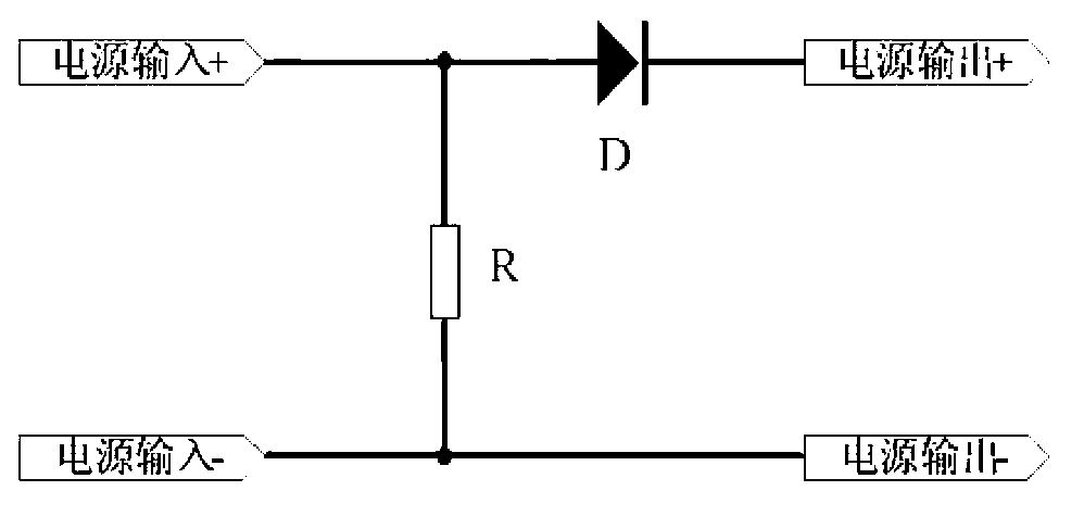
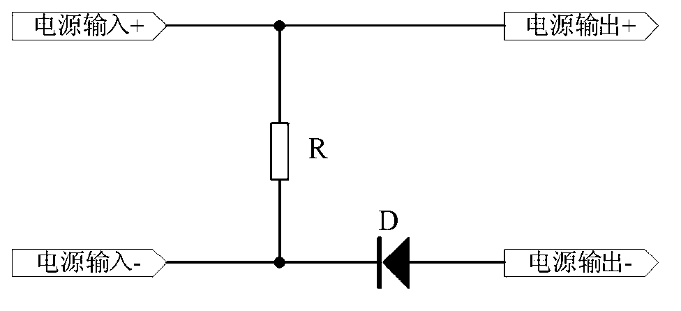
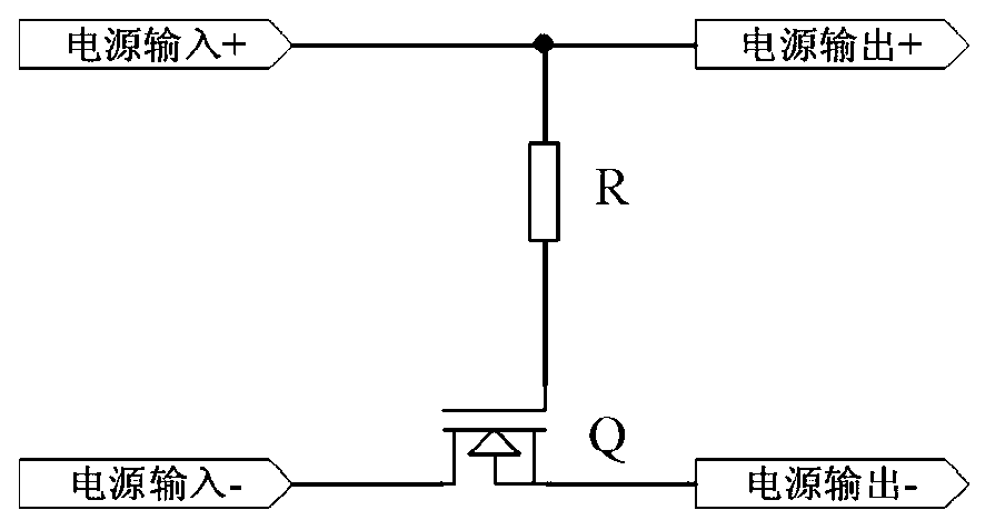
[0049] The decoding circuit of this embodiment is used when non-halogen lamps are used as vehicle lights. The decoding circuit is connected between the power supply and the non-halogen lamp. The structure diagram of the decoding circuit is as follows: Figure 4 As shown, the decoding circuit includes a decoding circuit control system, an anti-backflow prevention module for preventing circuit current backflow, a load simulation module for simulating the resistance load of a halogen lamp, and a filter module for preventing excessive charging current and serving as a filter. The anti-backflow module, the load simulation module and the filter module are electrically connected in sequence; the power input positive terminal and the power input negative terminal are electrically connected to the anti-backflow module, and the filter module is connected to the power output positive terminal and the power output negative terminal; the decoding circuit control system can be controlled by ...
Embodiment 3
[0058] The decoding circuit in this embodiment includes a decoding circuit control system, a backflow prevention module, a load simulation module and a filtering module. The anti-backflow module, the load simulation module and the filter module are electrically connected in sequence; the power input positive terminal and the power input negative terminal are electrically connected to the anti-backflow module, and the filter module is connected to the power output positive terminal and the power output negative terminal; the decoding circuit control system can be controlled by a microcomputer system or a control system composed of analog circuits, the output control one of the decoding circuit control system is connected to the load analog module, and the output control two of the decoding circuit control system is connected to the filter module.
[0059] Wherein, the load simulation module and the filter module adopt the structure of the second embodiment. The structure of the...
PUM
 Abstract
Description
Claims
Application Information
 - R&D
- Intellectual Property
- Life Sciences
- Materials
- Tech Scout
- Unparalleled Data Quality
- Higher Quality Content
- 60% Fewer Hallucinations
Browse by: Latest US Patents, China's latest patents, Technical Efficacy Thesaurus, Application Domain, Technology Topic, Popular Technical Reports.
© 2025 PatSnap. All rights reserved.Legal|Privacy policy|Modern Slavery Act Transparency Statement|Sitemap|About US| Contact US: help@patsnap.com


