Cooling fan with hydraulic motor mounting support

A technology for installing brackets and cooling fans, which is used in engine cooling, pump devices, non-variable-capacity pumps, etc. to improve strength and reliability, improve product performance, and reduce wind resistance.

Inactive Publication Date: 2013-09-04
HUNAN TYEN MACHINERY
View PDF0 Cites 4 Cited by
  • Summary
  • Abstract
  • Description
  • Claims
  • Application Information

AI Technical Summary

Problems solved by technology

If power is required to be input from the driven impeller end, the above structure cannot meet the requirements, and the installation position of the hydraulic motor needs to be considered

Method used


Image

  • Cooling fan with hydraulic motor mounting support
  • Cooling fan with hydraulic motor mounting support
  • Cooling fan with hydraulic motor mounting support

Examples


Embodiment Construction

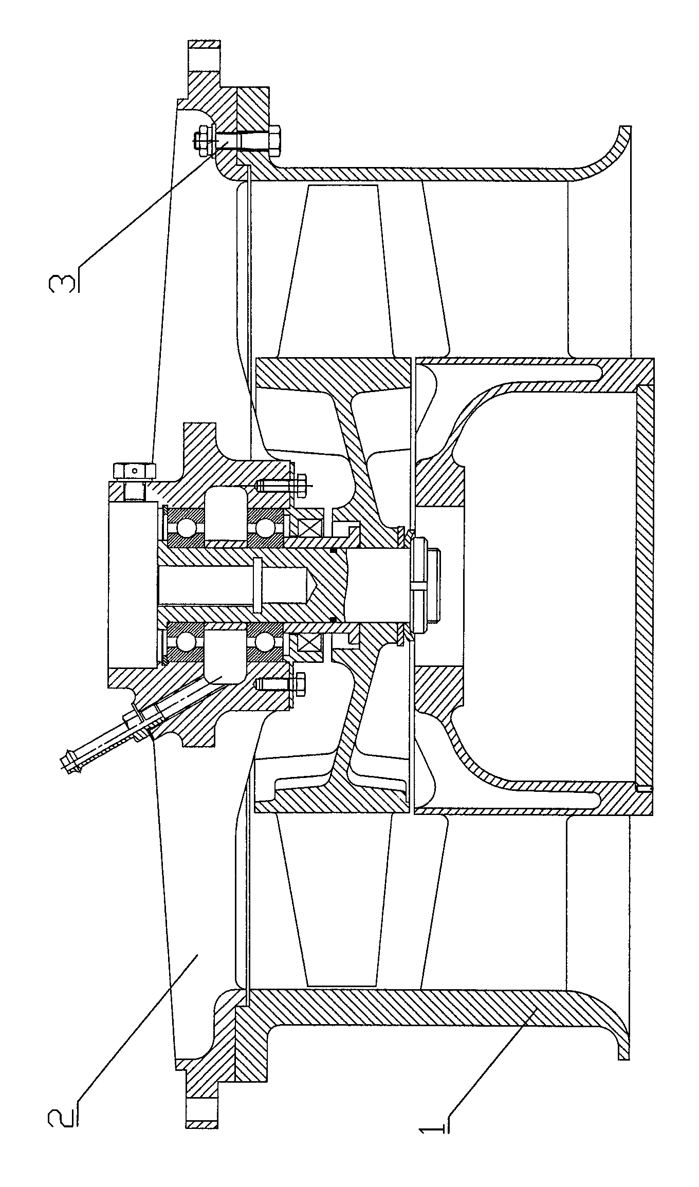
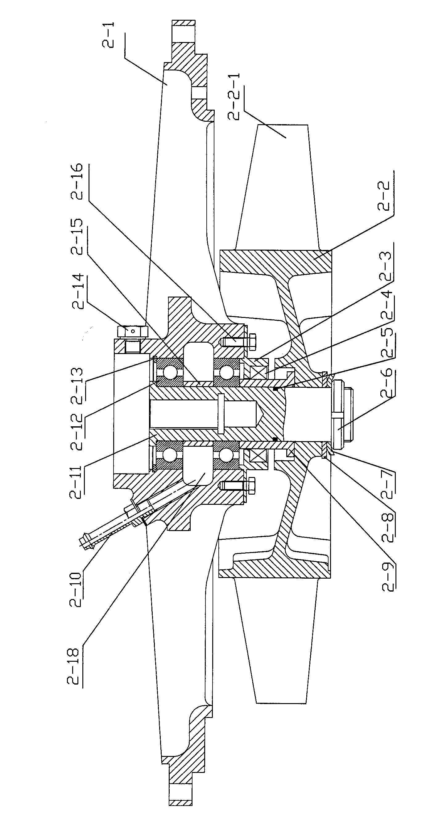
[0022] A cooling fan with a hydraulic motor mounting bracket is composed of a stationary impeller assembly 1 and a moving impeller assembly 2.

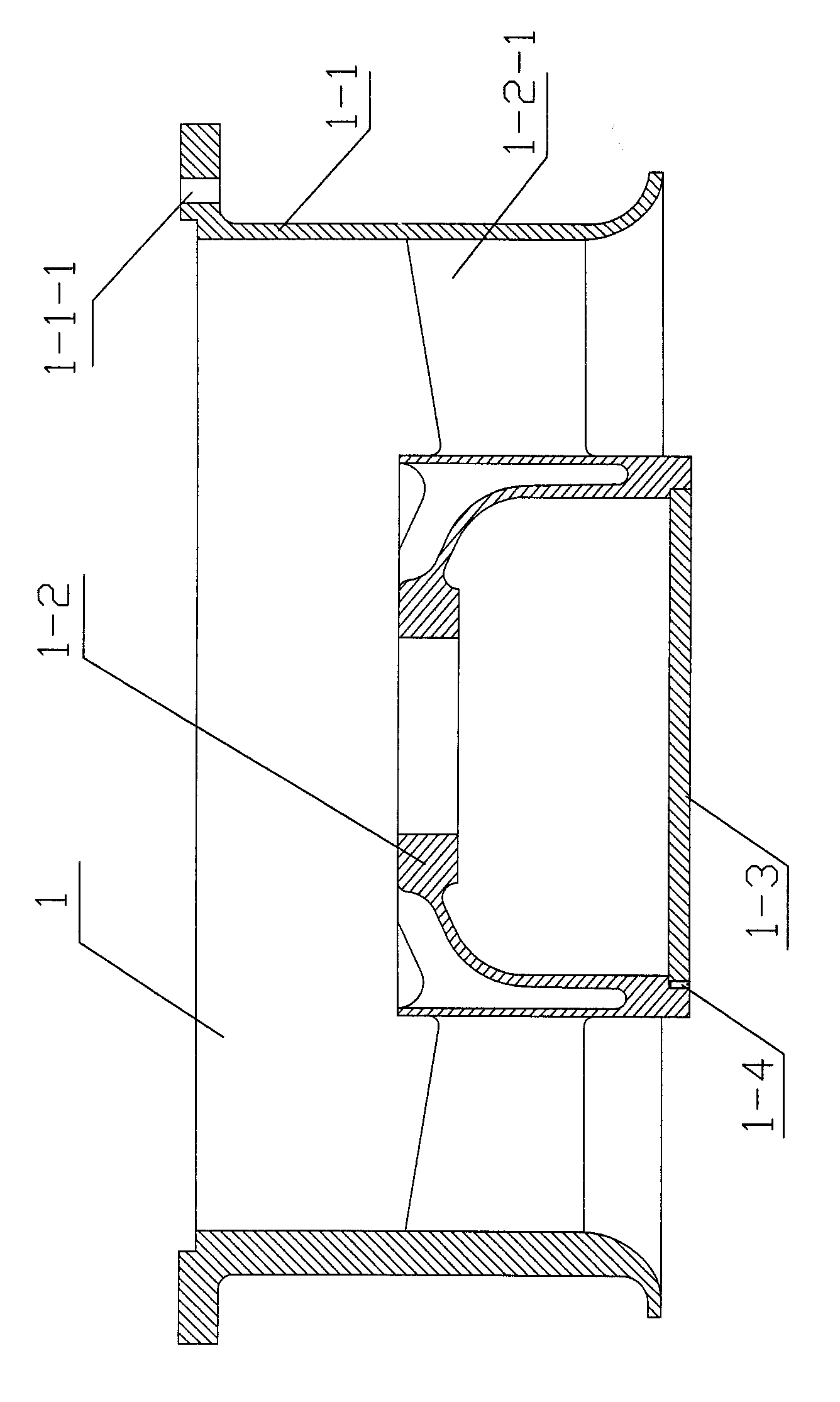
[0023] The stationary impeller assembly 1 is composed of a fixed ring 1-1, a stationary impeller 1-2, a cover plate 1-3 and a set screw 1-4. The fixing ring 1-1 is provided with a plurality of screw holes 1-1-1 for installing the bracket assembly 2, and the fixing ring 1-1 is also provided with a stepped hole 1-1 for installing the moving impeller assembly 2 -2, the outer circle of the stationary impeller 1-2 is provided with a plurality of stationary impeller blades 1-2-1, the stationary impeller blades 1-2-1 are evenly arranged on the outer circle of the stationary impeller 1-2, and the stationary impeller 1-2 is installed In the inner ring of the fixed ring 1-1, the stationary impeller 1-2 is pressed into the fixed ring 2-1 through the outer edge end surface of the stationary impeller blade 1-2-1 by hot pressing, and is connected w...


PUM


Abstract

A cooling fan with a hydraulic motor mounting support is composed of a fixed impeller assembly and a movable impeller assembly. The fixed impeller assembly comprises a fixed ring, a fixed impeller, a cover plate and a locking screw. The movable impeller assembly comprises a support, a movable impeller, a bearing cap, a framework oil seal, an O-shaped sealing ring, a fastening nut, a lock washer, a flat washer, a support sleeve, a lubricating nozzle, a fan shaft, two rolling bearings, an elastic collar, a breather plug, a bearing limit bush and a bolt, wherein the lubricating nozzle is sleeved with another flat washer, and the bolt is sleeved with a spring washer. During mounting the fixed impeller assembly and the movable impeller assembly, an annular mouth on an inner edge end face of a support hub of the movable impeller assembly is fastened into a step hole on the fixed ring of the fixed impeller assembly, and the movable impeller assembly and the fixed impeller assembly are integrally connected through the bolt. The cooling fan is of front-loaded fixed impeller and movable impeller structure, and the hydraulic motor is mounted on the movable impeller assembly to drive the movable impeller to rotate.

Description

technical field [0001] The invention relates to an engine cooling fan, in particular to an exhaust cooling fan driven by a hydraulic motor in a vehicle engine compartment. Background technique [0002] In recent years, a variety of new vehicles have improved the running speed, riding comfort and multi-functionality, which has led to the continuous increase of heat sources in the engine compartment and the continuous rise of temperature, which has a negative impact on the operation capacity of the entire equipment Great impact, so excess heat needs to be vented out of the engine bay through a fan. [0003] At present, there are various ways to drive the fan, such as motor drive, engine direct drive, and hydraulic drive. The motor drive needs to be connected to an external power supply, and the size of the motor is large, and the space structure requirements are limited; the direct drive of the engine is also limited by the space position; and the hydraulic motor drive is sim...

Claims


Application Information

Patent Timeline
Patent Type & Authority Applications(China)
IPC IPC(8): F04D25/04F01P5/02
Inventor 唐灵芝谢小丹陈文吴军伟王杨亚刘旭晶
Owner HUNAN TYEN MACHINERY
Why Eureka
Try Eureka