Power factor correction control circuit capable of reducing EMI

A power factor correction and control circuit technology, applied in the direction of output power conversion devices, electrical components, sustainable manufacturing/processing, etc., can solve problems such as difficult promotion and use, high peak value of inductor current, large inductor ripple current, etc., to achieve Reduced implementation cost and weight, guaranteed power factor, and increased switching frequency

Active Publication Date: 2014-11-05
SILERGY SEMICON TECH (HANGZHOU) CO LTD
View PDF4 Cites 0 Cited by
  • Summary
  • Abstract
  • Description
  • Claims
  • Application Information

AI Technical Summary

Problems solved by technology

from figure 1 It can be seen that the disadvantage is that the peak value of the inductor current is high, which will make the inductor ripple current larger, resulting in the need to strengthen the electromagnetic interference (EMI) filter in the circuit, increasing the input EMI Complexity of Filter Circuits
Moreover, the higher peak current will make the conduction loss of the semiconductor device larger
Therefore, in low-to-medium power applications, if you want to get the best performance, it will inevitably result in high cost and large volume, which is not easy to popularize and use.

Method used


Image

  • Power factor correction control circuit capable of reducing EMI
  • Power factor correction control circuit capable of reducing EMI
  • Power factor correction control circuit capable of reducing EMI

Examples


Embodiment Construction

[0037] Several preferred embodiments of the present invention will be described in detail below with reference to the accompanying drawings, but the present invention is not limited to these embodiments. The present invention covers any alternatives, modifications, equivalent methods and schemes made on the spirit and scope of the present invention. In order to provide the public with a thorough understanding of the present invention, specific details are set forth in the following preferred embodiments of the present invention, but those skilled in the art can fully understand the present invention without the description of these details.

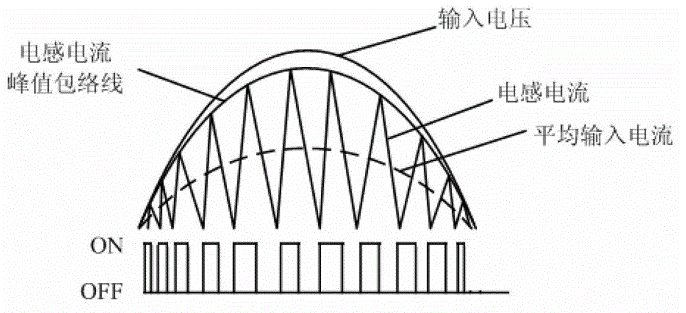
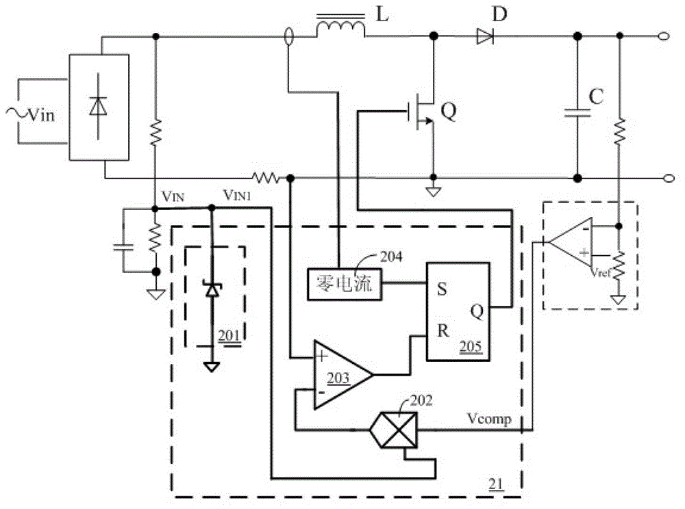
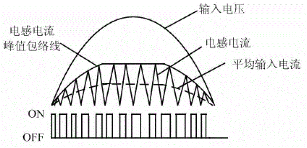
[0038]The power factor correction control circuit is mainly used in AC-DC converters. The AC input voltage of the AC-DC converter is passed through a rectification circuit to obtain a half-sine wave input voltage. The power factor correction control circuit is used to control the AC-DC converter. The state of the power switch tube in the ...


PUM


Abstract

The invention discloses a power factor correction control circuit capable of reducing EMI. The control circuit comprises an inductive current threshold value, the peak value of the inductive current is controlled to change along with the input voltage when the inductive current is smaller than the inductive current threshold value, and the inductive current is restrained to the inductive current threshold value when the inductive current reaches the inductive current threshold value. Therefore, the maximum peak of the inductive current is reduced in the above manner, and the inductive ripple current is reduced. The power factor is guaranteed, at the same time, the EMI of the circuit is reduced, the circuit filter task is conducted simply and easily, and the power factor correction control circuit is suitable for sites of medium power and small power. The peak current stress of the circuit is low, a switch tube and other elements wear little, and the power utilization rate is improved further. The power factor correction control circuit capable of reducing the EMI meets the requirements on power supply harmonics of high-efficient factors and IEC61000-3-2, and is low in cost and small in size.

Description

[0001] This application is a divisional application with the application number 201110289647.7, the application date is September 14, 2011, and the invention title is "A Power Factor Correction Control Circuit for EMI Reduction". technical field [0002] The invention relates to the field of power supplies, and more specifically relates to a power factor correction control circuit for reducing EMI. Background technique [0003] In the application of AC / DC power supply, in order to achieve high power factor, a power factor correction (Power Factor Correction, PFC for short) function is usually designed in the circuit. Currently, a critical conduction mode power factor correction circuit is more commonly used. From the perspective of implementation, there are two solutions for the existing critical conduction mode: one is the peak current mode, and the other is the voltage mode. The former scheme uses the peak value of the modulated inductor current to follow the change of the...

Claims


Application Information

Patent Timeline
Patent Type & Authority Patents(China)
IPC IPC(8): H02M1/42H02M1/44H02M1/12
CPCY02B70/126Y02B70/10Y02P80/10
Inventor 陈伟
Owner SILERGY SEMICON TECH (HANGZHOU) CO LTD
Why Eureka
Try Eureka