Electrical-control vehicle-mounted capping mechanism device for hot metal ladle

An electronically controlled vehicle and iron-carrying technology, applied in metal processing equipment, casting melt containers, casting equipment, etc., can solve the problems of low reliability, heat loss, large overall quality, etc., to improve safety and reliability, High environmental adaptability, the effect of reducing heat loss

Inactive Publication Date: 2013-09-11
DALIAN UNIV OF TECH +2
View PDF4 Cites 4 Cited by
  • Summary
  • Abstract
  • Description
  • Claims
  • Application Information

AI Technical Summary

Problems solved by technology

[0003] The existing iron clad capping mechanism has the following shortcomings: 1. The overall mass of the iron clad closing / opening action is too large, exceeding the carrying capacity of the hauling train, affecting driving safety and service life; 2. Lack of self-positioning Function, when there is sticky sand at the ladle mouth, the tight fit between the ladle cover and the iron ladle cannot be realized, resulting in heat loss and reducing economic benefits; 3. Adopting hydraulic drive, it has a greater impact in the high-temperature working environment of loading, unloading and transporting molten iron. safety hazard, low reliability

Method used


Image

  • Electrical-control vehicle-mounted capping mechanism device for hot metal ladle
  • Electrical-control vehicle-mounted capping mechanism device for hot metal ladle

Examples


Embodiment

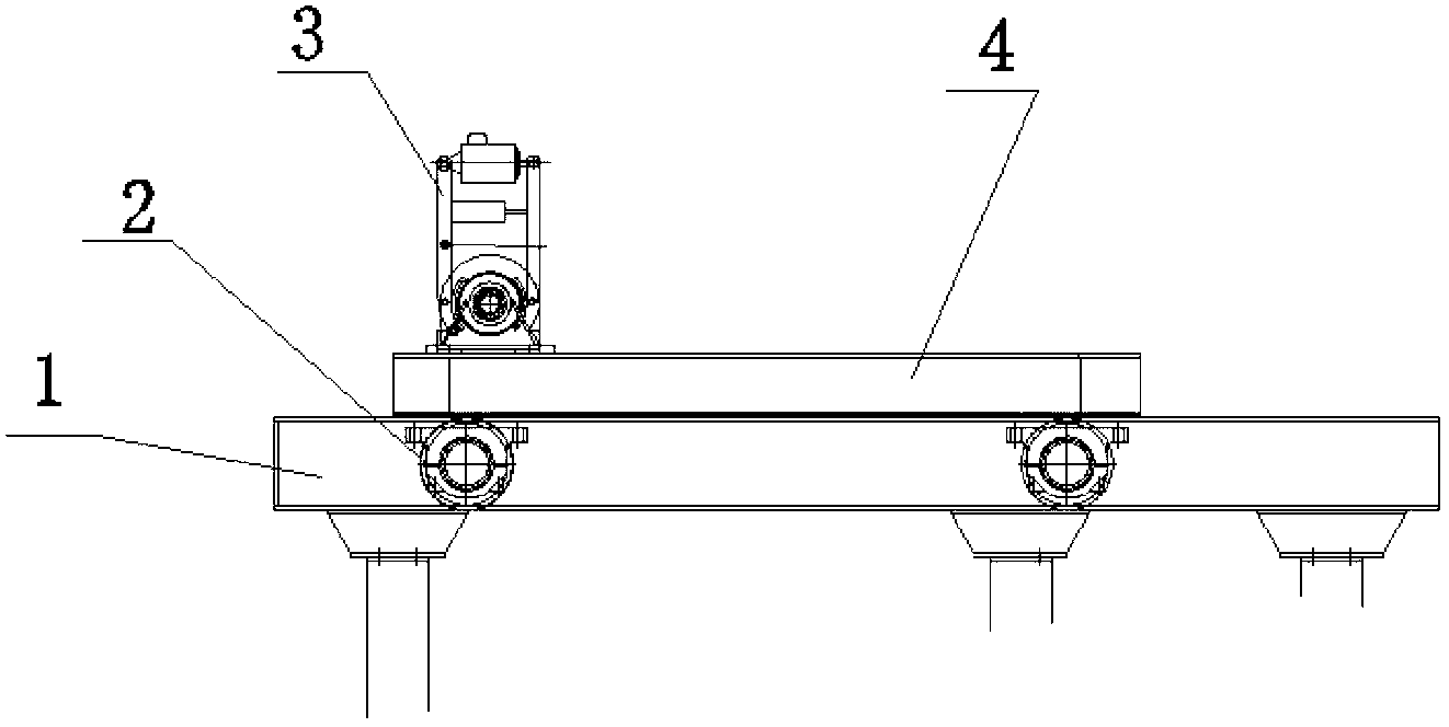
[0016] Such as figure 1 Shown is the schematic diagram of the trolley mechanism of the present invention. The driving motor 3 is installed on the frame 4. When the driving motor is working, its output shaft is driven by a pair of external gears, so that the active wheel set and the passive wheel set 2 run in the guide rail 1, thereby driving the whole trolley to move horizontally.

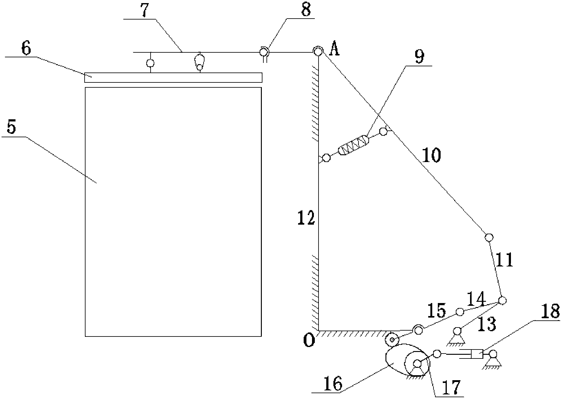
[0017] Such as figure 2 Shown is a schematic diagram of the electric rod mechanism assembly / opening process of the present invention. Electric push rod 18, crank 17 and drive cam 16 constitute a push rod-cam mechanism; connecting rod A13, connecting rod B14, connecting rod B15 and frame 12 constitute an inner ring double rocker four-bar mechanism; opening and closing rocker arm 10 , connecting rod A11, connecting rod A and the frame form an outer ring double rocker four-bar mechanism; the two ends of the auxiliary balance spring 9 are hinged on the opening and closing rocker arm 10 and the frame...


PUM


Abstract

The invention relates to an electrical-control vehicle-mounted capping mechanism device for a hot metal ladle. The electrical-control vehicle-mounted capping mechanism device adopts a motor as a power source and a trolley / cam linkage mechanism as an actuating mechanism to realize horizontal movement and achieve the function of capping / uncapping as required, thereby reducing heat loss of liquid steel and obtaining more economic benefits. The invention realizes safety, reliability and adaptability of the capping mechanism of the hot metal ladle in operation by virtue of the felicitous coordination of all rod group mechanisms. The electrical-control vehicle-mounted capping device comprises three main parts, namely a rail guided trolley mechanism, an electric rod group mechanism and a ladle cap mechanism. The working principle of the electrical-control vehicle-mounted capping mechanism device is that the motor drives the trolley to move to realize the horizontal movement of a ladle cap, and through the combination of an electric push rod-drive cam mechanism and the linkage mechanism, a capping / uncapping action is realized so as to enable the hot metal ladle to be closely covered with the ladle cap. A slotted hole is formed in the ladle cap; and in coordination with the linkage mechanism, the ladle cap still can be closely fitted with the hot metal ladle on the condition that the hot metal ladle expands and sand sticks to the edge of the iron ladle.

Description

technical field [0001] The invention relates to a mechanism device for electronically controlling vehicle-mounted iron ladle capping. Its principle is to use a motor as a power source, and use a trolley / rod group structure as an actuator to achieve the required horizontal movement with the minimum power, materials and cost. And the lid closing / opening function, so that without changing the existing factory building and equipment, the iron ladle can be covered on the molten steel hauling train, adapting to the new process of one ladle to the end, reducing the heat loss of molten steel, and achieving a higher economic benefits. Background technique [0002] The electronically controlled vehicle-mounted iron ladle capping mechanism is mainly composed of three parts: a trolley mechanism, an electric rod group mechanism and a capping mechanism. Its working principle is to realize the horizontal movement of the cover through the movement of the trolley, and realize the closing / op...

Claims


Application Information

Patent Timeline
Patent Type & Authority Applications(China)
IPC IPC(8): B22D41/00
Inventor 王德伦董惠敏张春利尚振国吴煜娜仁杨丽华吕晓宇孟茹孙大庆
Owner DALIAN UNIV OF TECH
Why Eureka
Try Eureka