Clamping mechanism

A technology of clamping mechanism and clamping part, which is applied in the direction of clamps, clamping, workpiece clamping devices, etc., can solve the problems of reducing work efficiency and complicated clamping operation, and achieves improved work efficiency, simple structure, and reduced labor. The effect of intensity

Inactive Publication Date: 2013-09-11
JINCHENG FUTAIHUA PRECISION ELECTRONICS CO LTD
View PDF8 Cites 11 Cited by
  • Summary
  • Abstract
  • Description
  • Claims
  • Application Information

AI Technical Summary

Problems solved by technology

However, this kind of clamping mechanism needs to rotate the screw rod when clamping the workpiece or product, which makes its clamping operation complicated, and its work efficiency will be greatly reduced when performing frequent clamping and loosening operations

Method used


Image

  • Clamping mechanism
  • Clamping mechanism
  • Clamping mechanism

Examples


Embodiment Construction

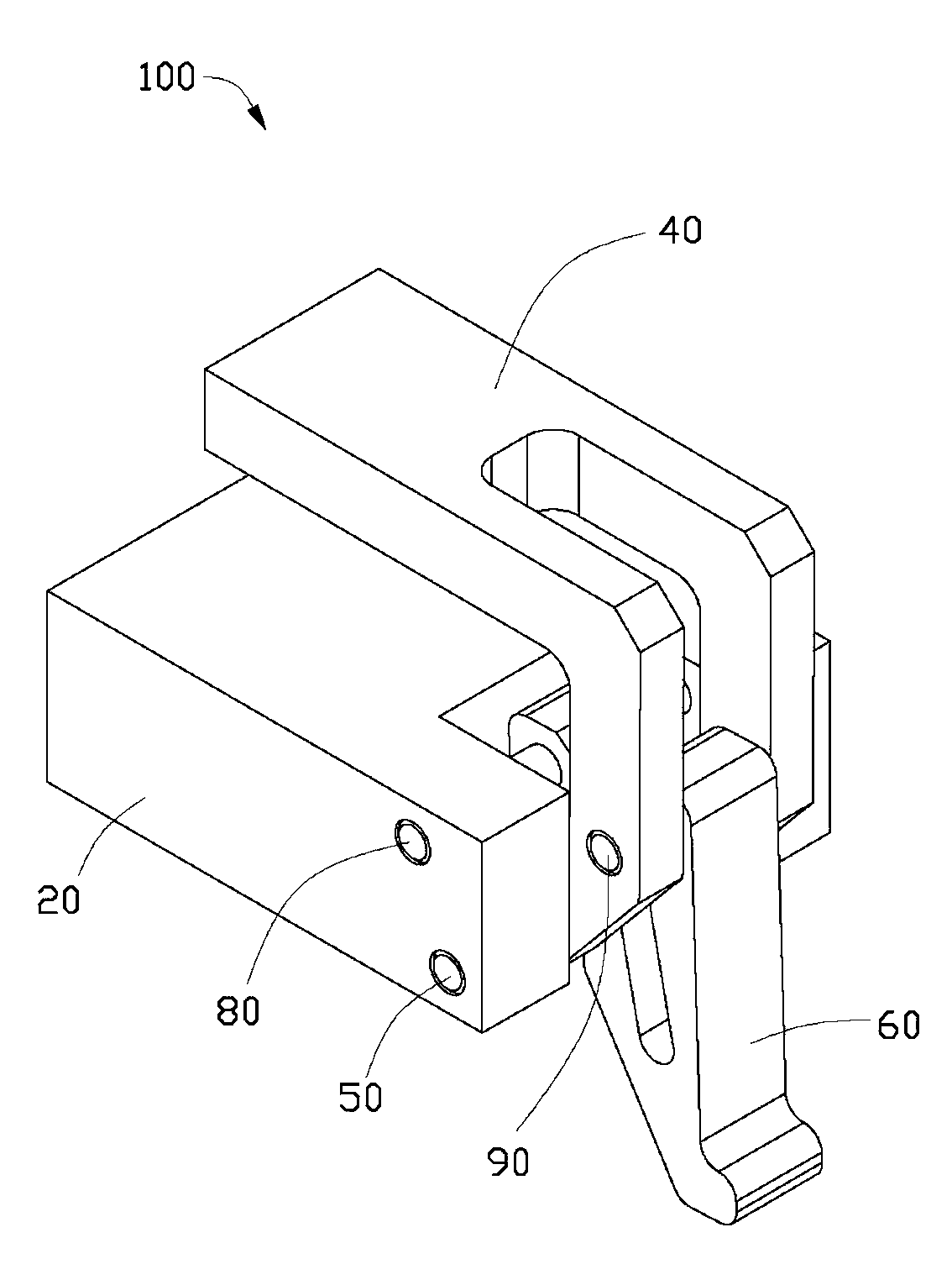
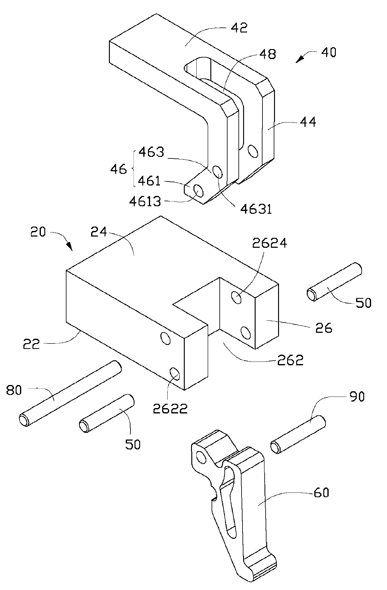
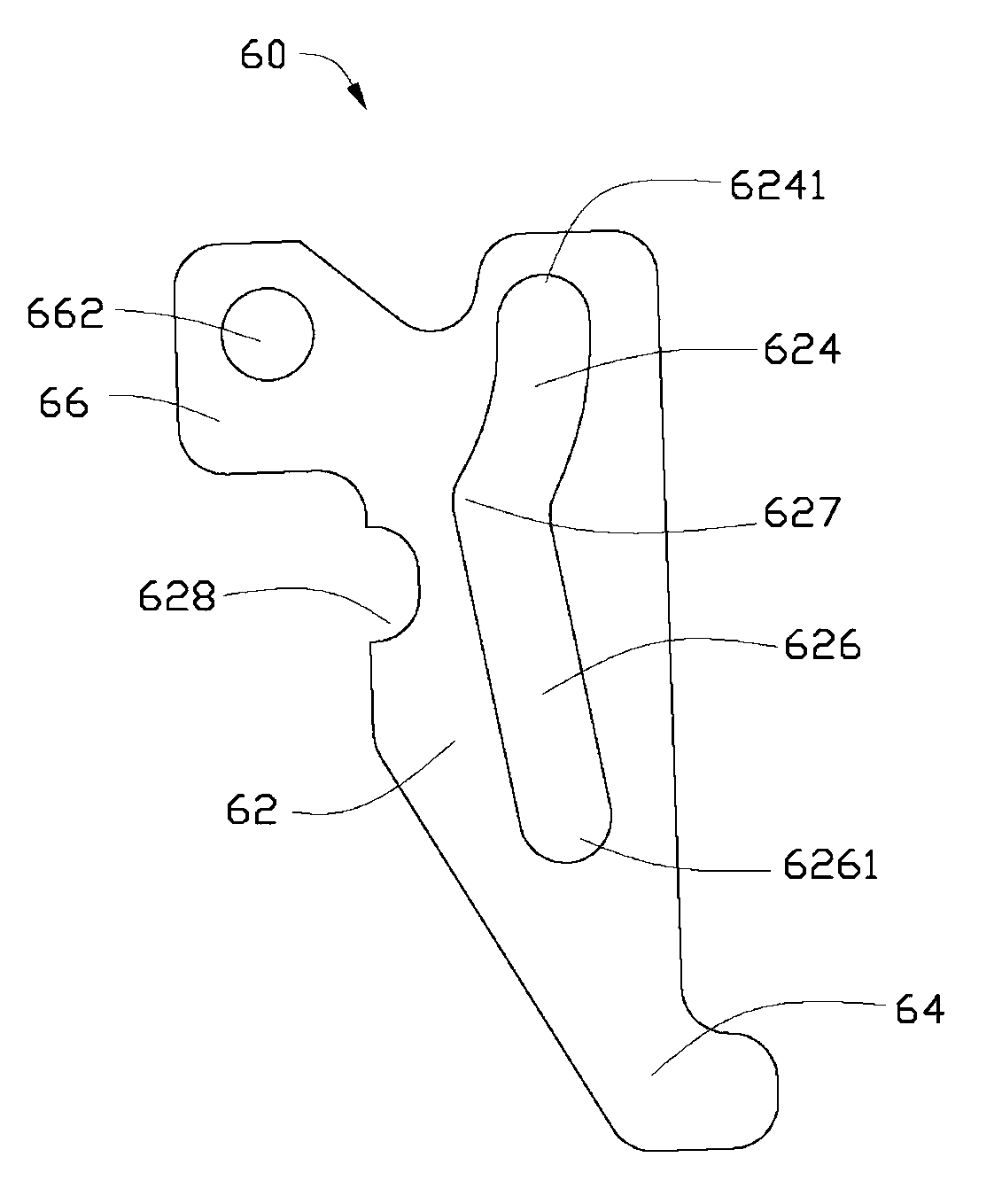
[0015] see figure 1 and figure 2 , the clamping mechanism 100 of this embodiment is used for workpiece 200 (such as Figure 4 shown) for quick loading and unloading, which includes a base 20 , a pressing block 40 , two pivots 50 , an eccentric handle 60 , a rotating shaft 80 and a guide 90 . The pressing block 40 is rotatably connected with the base 20 through two pivots 50 . The eccentric wheel handle 60 is relatively rotatably hinged with the base 20 through the rotating shaft 80, and is movably connected with the pressure block 40 through the guide 90, so as to control the rotation of the pressure block 40 around the base 20 to clamp or release the mounting on the base 20 Workpiece 200 on. In this embodiment, the pivot 50 , the rotating shaft 80 and the guide 90 are all rod-shaped pins.

[0016] The base 20 is roughly block-shaped, and includes a bottom surface 22 , a mounting top surface 24 and a side surface 26 opposite to the bottom surface 22 . It can be understoo...


PUM


Abstract

A clamping mechanism comprises a base, a pressing block, an eccentric wheel handle and a guide part, wherein the pressing block is in rotational connection with the base; a hinged hole and an arc-shaped slide groove which is eccentrically formed relative to the hinged hole are formed in the eccentric wheel handle; the eccentric wheel handle is hinged with the base through the hinged hole; and the guide part is arranged in the arc-shaped slide groove of the eccentric wheel handle in a penetrating manner and movably connected with the pressing block, so as to control the pressing block to rotate around the base, and then a workpiece mounted on the base is clamped or released. According to the clamping mechanism provided by the invention, the structure is simple, all that is needed is to perform simple operation on the eccentric wheel handle, then the rapid loading and unloading of workpieces can be achieved, the work efficiency is improved, and the labor intensity is reduced.

Description

technical field [0001] The invention relates to a clamping mechanism, in particular to a clamping mechanism capable of quickly loading and unloading workpieces. Background technique [0002] In the production process, it is usually necessary to use a clamping mechanism to clamp the workpiece or product to facilitate the assembly or transportation of the workpiece or product. Most of the current clamping mechanisms have a briquetting block and a base, and the distance between the briquetting block and the base is usually adjusted by screw driving, so as to realize the clamping of workpieces or products between the briquetting block and the base. However, this kind of clamping mechanism needs to rotate the screw rod when clamping the workpiece or product, which makes its clamping operation complicated, and its work efficiency will be greatly reduced when performing frequent clamping and loosening operations. Contents of the invention [0003] In view of the above, it is nec...

Claims


Application Information

Patent Timeline
Patent Type & Authority Applications(China)
IPC IPC(8): B25B11/00
CPCB25B5/08B23Q3/069
Inventor 文青松
Owner JINCHENG FUTAIHUA PRECISION ELECTRONICS CO LTD
Why Eureka
Try Eureka