Self-control heating device for railway insulating tanker

A technology for tank cars and railways, which is applied to the field of self-controlled heating devices of railway thermal insulation tank cars, can solve the problems that the heating method and thermal insulation performance cannot meet the requirements for the shipment of chemical raw materials, are not suitable for the shipment of fine chemical raw materials, and have low transportation efficiency, and can avoid problems such as The local temperature is too high, the unloading operation time is saved, and the heating efficiency is high.

Active Publication Date: 2015-06-24
CRRC MEISHAN
View PDF7 Cites 0 Cited by
  • Summary
  • Abstract
  • Description
  • Claims
  • Application Information

AI Technical Summary

Problems solved by technology

The chemical raw material has strict requirements on storage and transportation. At present, the transportation of the chemical raw material is mainly carried out in tank containers or drums with thermal insulation and heating devices. The transportation efficiency is low. The use of railway tanker transportation can greatly improve the transportation efficiency and save transportation costs.
The existing tank cars with heat preservation and heating functions in China are mainly asphalt tank cars. Asphalt tank cars use built-in fire tube heating and external glass wool for heat preservation. The heating method and heat preservation performance cannot meet the shipping requirements of this chemical raw material; It is made of carbon steel, which is easy to rust and pollute the goods transported, and it is not suitable for the shipment of fine chemical raw materials
At present, it is still blank to transport this kind of chemical by railway tanker in China

Method used


Image

  • Self-control heating device for railway insulating tanker
  • Self-control heating device for railway insulating tanker
  • Self-control heating device for railway insulating tanker

Examples


Embodiment Construction

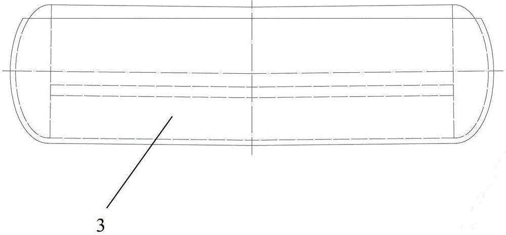
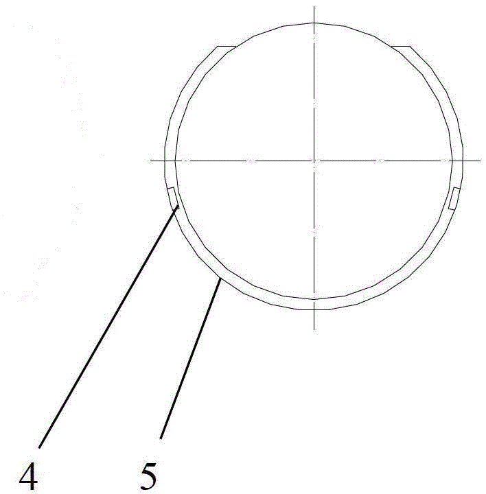
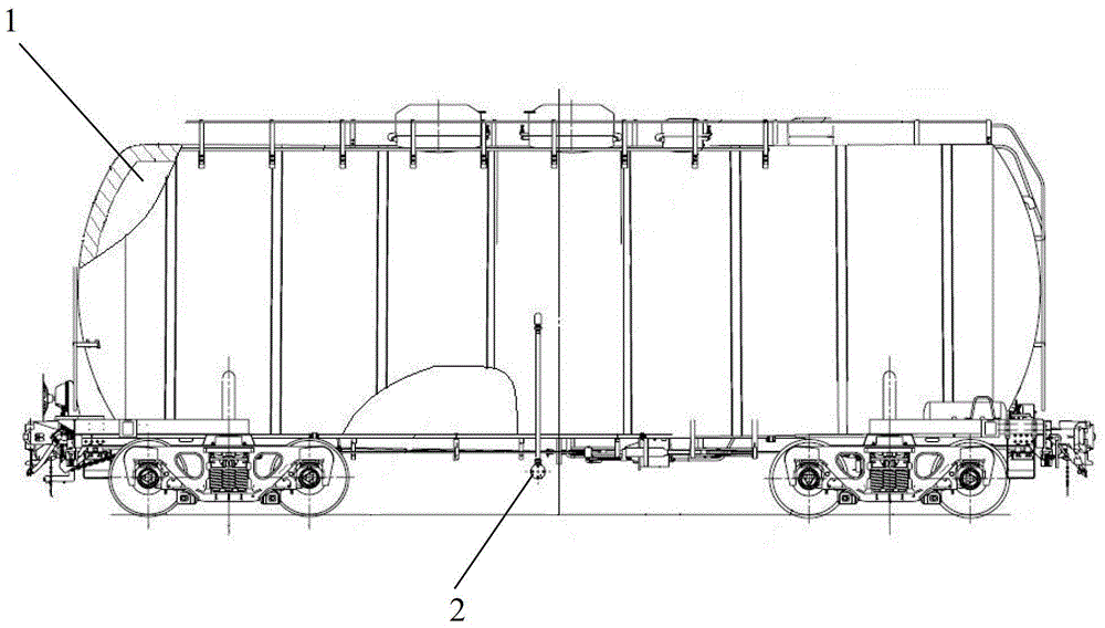
[0014] see Figure 1 to Figure 5 , the present invention includes a steam heating jacket 3 and a steam heating control system 2, the steam heating jacket 3 is arranged on the outer surface of the tank body 1 of the railway insulation tank car, and includes a steam heating cover 5 and a steam distribution groove 4, and the steam distribution groove 4 is a groove Type upper and lower opening structure (such as Figure 5 shown), arranged along the longitudinal length of the tank body 1, welded to the inner wall of the steam heating cover 5, without direct contact with the tank body, and the steam heating control system 2 has a steam pipe leading to the steam distribution tank 4.

[0015] The heating area of ​​the steam heating jacket 3 reaches 70%-80% of the outer surface area of ​​the tank body 1 .

[0016] The steam heating control system 2 includes a steam pipe on which a stop valve 6, a filter 7 and a self-acting temperature control valve 8 are installed. The self-acting tem...


PUM


Abstract

The invention relates to a self-control heating device for a railway insulating tanker and relates to a railway tanker with insulating structure. The self-control heating device comprises a steam heating jacket and a steam heating control system. The steam heating jacket is arranged on the outer surface of a tank body of the railway insulating tanker and comprises a steam heating cover and steam distribution channels. Each steam distribution channel in a channel structure with top and bottom holes is longitudinally arranged lengthwise along the tank body and welded to the inner wall of the steam heating cover without direct contact with the tank body. The steam heating control system is provided with a steam pipe leading to the steam distribution channels. The self-control heating device has the advantages that the steam distribution channels are arranged on the inner wall of the insulating jacket, so that steam can be distributed fast in the heating jacket, local excessively-high temperature is avoided, even heating can be realized, and heating efficiency is improved; unloading can be completed by not heating or slightly heating according to weather, so that unloading time is saved; the problems in railway transporting of fine chemical raw materials easy to solidify at normal temperature in the background art are solved.

Description

technical field [0001] The utility model relates to a self-control heating device for a railway thermal insulation tank car, which relates to a railway tank vehicle with a thermal insulation structure. Background technique [0002] Certain organic chemical and fine chemical raw materials are in a solidified state when the temperature is lower than 20°C, and can be turned back into a liquid state by heating. The heating temperature must be controlled in order not to affect its properties. The chemical raw material has strict requirements on storage and transportation. At present, the transportation of the chemical raw material is mainly carried out in tank containers or drums with thermal insulation and heating devices. The transportation efficiency is low. The use of railway tanker transportation can greatly improve the transportation efficiency and save transportation costs. . The existing tank cars with heat preservation and heating functions in China are mainly asphalt t...

Claims


Application Information

Patent Timeline
Patent Type & Authority Patents(China)
IPC IPC(8): B65D88/74
Inventor 李强林结良彭燎陆强
Owner CRRC MEISHAN
Why Eureka
Try Eureka