Chain transmission

A technology of chain transmission and chain, which is applied in the direction of transmission device, transmission chain, belt/chain/gear, etc., and can solve the problem of not being able to reduce the assembly burden of roller chain 510

Inactive Publication Date: 2013-09-11
TSUBAKIMOTO CHAIN CO
View PDF6 Cites 4 Cited by
  • Summary
  • Abstract
  • Description
  • Claims
  • Application Information

AI Technical Summary

Problems solved by technology

[0005] In addition, when assembling the roller chain 510, it is necessary to press and fit the end portion 515a of the bush 515 into the bush hole 514a of the inner connection plate 514 with a strong pressure, so there is a problem that the assembly of the roller chain 510 cannot be lightened. Burden problem

Method used


Image

  • Chain transmission
  • Chain transmission
  • Chain transmission

Examples


Embodiment Construction

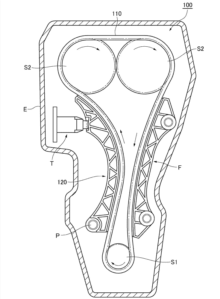
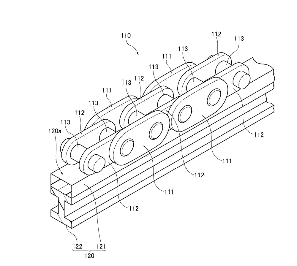
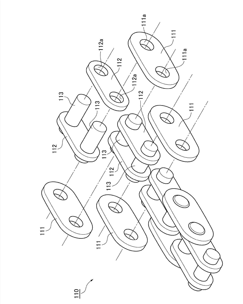
[0069] The chain transmission device of the present invention has a pair of left and right outer chain plates which are alternately combined in the chain length direction and freely connected by connecting pins and arranged separately in the chain width direction, and between the left and right outer chain plates along the chain width. A transmission chain composed of a pair of left and right inner link plates arranged separately in direction, and a chain guide for slidingly connecting and moving the transmission chain along the chain length direction. The structure of the transmission chain is: press-fit connecting pins into the pin press-in holes provided on the pair of left and right inner chain plates, and loosely insert them into the pin loose sleeve holes provided on the pair of left and right outer chain plates Connecting pins, which can permanently suppress the elongation of the chain due to the bending of the connecting pins, at the same time, reduce the assembly load ...


PUM


Abstract

The invention discloses a chain transmission 100. The transmission chain 110 of the chain transmission is configuered so that a right and left outer plate 111,111 and a right and left inner plate 112,112 being spaced from each other in the direction of the width of the chain and are freely bent connected with each other through press-fitting connecting pins 113. Press-fitting connecting pins 113 are inserted into press-fitting holes 112a in the right and left inner plates 112,112; and Connecting pins 113 are inserted closely, but are rotatable in holes 111a in the right and left outer plate 111,111. Therefore, it is possible to reduce deflection of the connecting pins and to suppress elongation of the chain caused by the deflection of the connecting pins for a long time, and reduce the assembly load and power transmission load, and downsizing the assembly size of the chain transmission.

Description

technical field [0001] The present invention relates to a chain transmission having a transmission chain for transmitting power, a chain guide for moving the transmission chain in sliding connection, and a sprocket engaged with the transmission chain. Background technique [0002] like Figure 13 and Figure 14 As shown, for the existing chain transmission device 500, the well-known configuration is to have a roller chain 510, a chain guide 520 that enables the roller chain 510 to move in a sliding connection along the length direction of the chain, and a chain guide 520 corresponding to the roller chain 510. Engaged sprockets (not shown). The roller chain 510 has an outer link unit 513 formed by pressing a connecting pin 512 into the pin holes 511a of a pair of left and right outer connecting plates 511, 511, and a bushing hole 514a of a pair of left and right inner connecting plates 514, 514. The inner link unit 516 formed by pressing the bush 515 in the middle; by inser...

Claims


Application Information

Patent Timeline
Patent Type & Authority Applications(China)
IPC IPC(8): F16H7/06F16H7/18F16G13/06
CPCF16G13/06F16H7/18
Inventor 横山正则
Owner TSUBAKIMOTO CHAIN CO
Why Eureka
Try Eureka